Method for measuring conditions in a power boiler furnace using a sootblower

a technology of sootblower and power boiler furnace, which is applied in the direction of furnaces, instruments, lighting and heating apparatus, etc., can solve the problems of reducing the efficiency of the recovery furnace, the accumulation of deposits will be difficult to remove, and the dust-like particles will be harder to sinter and/or harden, etc., to achieve easy interpretation, control the recovery process, and high efficiency

Active Publication Date: 2011-03-10
SOOTTECH AB
View PDF6 Cites 14 Cited by
  • Summary
  • Abstract
  • Description
  • Claims
  • Application Information

AI Technical Summary

Benefits of technology

[0013]According to another aspect of the invention, the measuring takes place at the same time as the lance tube of the sootblower is used for cleaning the recovery furnace. Thereby, maximum efficiency of the sootblower is achieved, since no separate operation of the lance of the sootblower is needed for the measuring process.
[0024]According to another aspect of the invention, the information obtained thanks to the invention is used to automatically control various properties of the process in the furnace, such as the distribution of air between the openings of the furnace, controlling the dampers, or burners, the combustion air flow, pressures and distribution, liquor gun angles, liquor / fuel temperature, fuel pressure. Thereby, the recovery process can be controlled and a higher efficiency be achieved thanks to the information yielded by the invention.

Problems solved by technology

As the recovery furnace operates as a chemical reactor, the combustion conditions differ from those of an ordinary boiler, in that the heating surfaces of the furnace get covered extremely rapidly with combustion deposits, i.e. carryover / slag, dust and / or soot, which decrease the efficiency of the recovery furnace, particularly by reducing heat transfer in the furnace.
If the time between successive cleanings in the furnace is too long, the dust-like particles get harder and / or sinter, and the deposits will be harder to remove.
However, to achieve the desired results is difficult due to the extreme temperatures and chemical conditions in the furnace and the fact that any sensors provided inside the furnace would themselves have to be cleaned from the soot or sintered dust from the process.
However, the technology does not disclose a method or device for measuring the conditions inside the furnace itself, and therefore does not present a reliable solution to the problem of monitoring or controlling the operation of said furnace.
The sensors are, however, placed inside the furnace itself, and so are themselves subject to the extreme conditions mentioned above.
This severely limits the types of sensors that can be used, as well as the data that can be retrieved from them, and does not allow for detailed monitoring and control over the process inside the furnace.
These methods therefore all suffer from the lack of accuracy which arises when sensors are present in the highly chemical environment of the recovery furnace.
They are also expensive due to the need of machinery that handles large probes of lengths around 4-8 m.
Inside the furnace a great amount of opaque flue gas obstructs the view, rendering it impossible to use ordinary measuring instruments to measure anything but the band of flue gas close to the wall of the furnace.
Thus, no detailed information of the conditions towards the middle of the furnace can be achieved.

Method used


Image

  • Method for measuring conditions in a power boiler furnace using a sootblower
  • Method for measuring conditions in a power boiler furnace using a sootblower
  • Method for measuring conditions in a power boiler furnace using a sootblower

Examples


Embodiment Construction

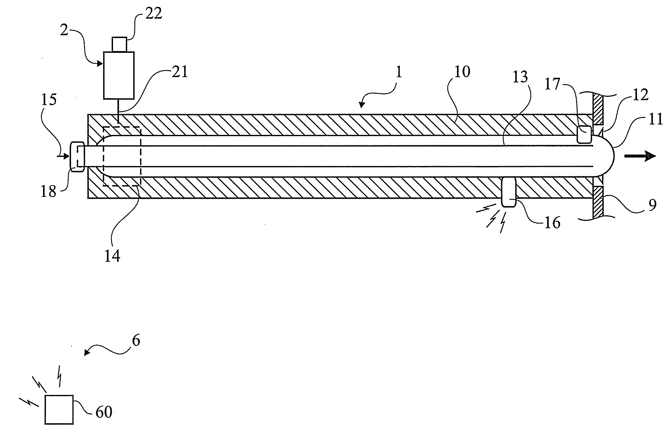
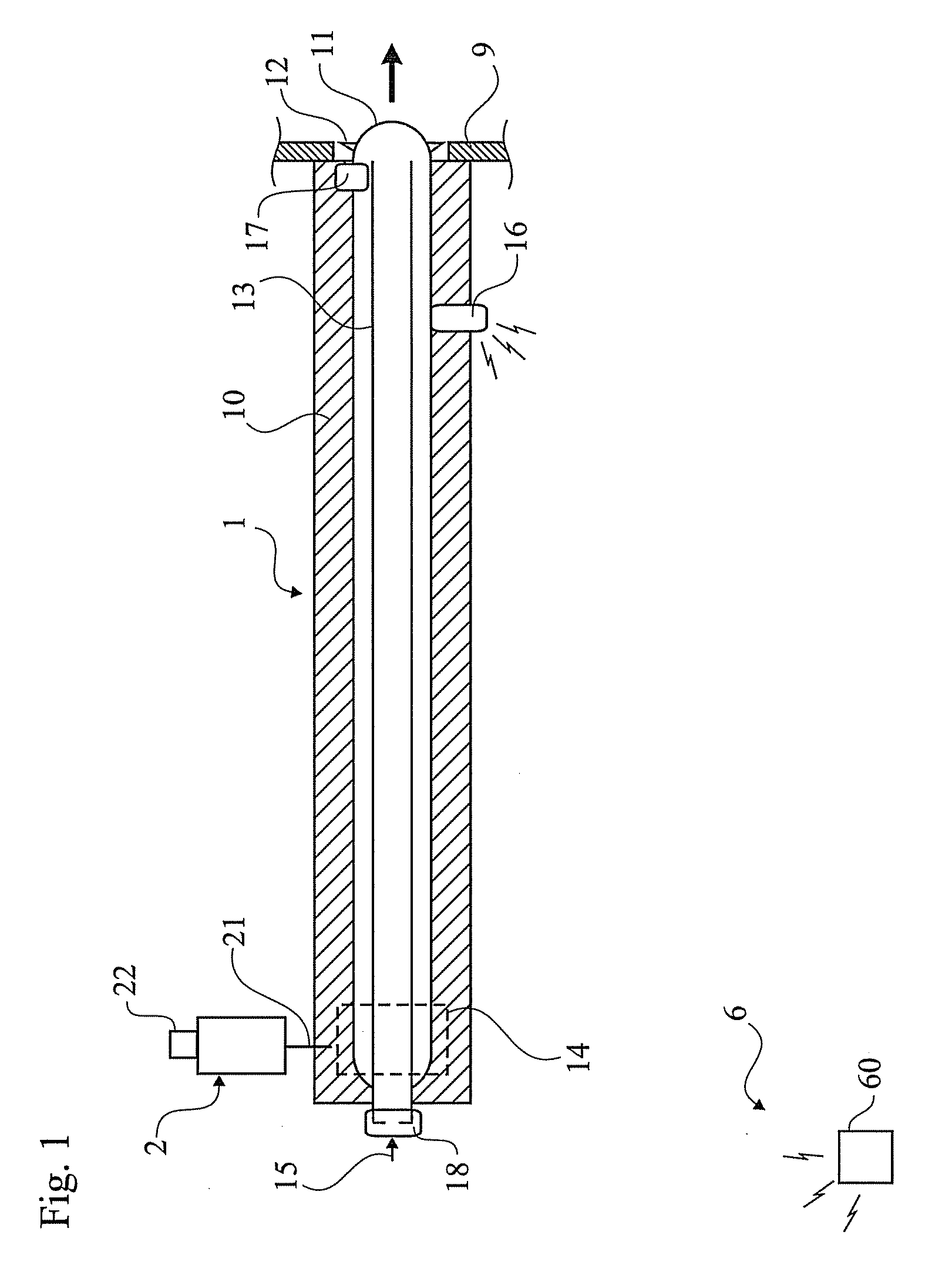
[0033]FIG. 1 shows a schematic view of a sootblower arrangement 1, having a lance tube 11 retracted into an end position and just starting its insertion into the recovery furnace, the outer wall of which is designated 9. The sootblower arrangement 1 includes a frame 10, a moveable carriage 14 supported by the frame 10, and a motor 2 for moving the carriage (in a manner not shown) via a drive shaft 21. The lance tube 11 is mounted on the carriage 14 to be insertable into and retractable from the recovery furnace, and it has at least one but preferably two nozzles 12 for ejecting steam. The lance tube 11 surrounds an interior steam feed tube 13, to which an external steam feed tube (indicated by the arrow 15) is connected for feeding sootblowing steam to be ejected through said at least one lance tube nozzle 12 into the recovery furnace. A sensor 16 is mounted in the frame 10 for taking measurements on the segment of the surface of the lance shaft 11 closest to said sensor 16, and sen...


PUM


Abstract

The present invention relates to a method for measuring the conditions inside a power boiler wherein a sootblower is used as a measuring probe. The invention also relates to a system for measuring the conditions in a power boiler, comprising a control unit, at least one sensor and a measuring probe placed inside said furnace, wherein said probe is arranged on a soot blower.

Description

TECHNICAL FIELD[0001]The present invention relates to a method for measuring the conditions inside a power boiler furnace.BACKGROUND ART[0002]In pulp industry, recovery furnaces are used as a chemical reactor and for the production of steam for internal use, for generation of electricity, and for sale. As the recovery furnace operates as a chemical reactor, the combustion conditions differ from those of an ordinary boiler, in that the heating surfaces of the furnace get covered extremely rapidly with combustion deposits, i.e. carryover / slag, dust and / or soot, which decrease the efficiency of the recovery furnace, particularly by reducing heat transfer in the furnace. In addition to soot, the flue gases contain inorganic chemicals, which condense on the heating surfaces of the recovery furnace.[0003]In power boilers the thermal and chemically efficiency is normally depending on the mixture of fuel, combustible gases and the air in the furnace. In larger furnaces, there are local vari...

Claims


Application Information

Patent Timeline
Patent Type & Authority Applications(United States)
IPC IPC(8): G01D21/00
CPCF01K13/003F23J3/023F23N5/003F28G15/003F27D21/0014F27D21/02F28G1/16F27D21/00
Inventor DAHLEN, ERIKNIKLASSON, MIKAEL
Owner SOOTTECH AB
Why Eureka
Try Eureka