
Full time regenerative type single radiant tube burner

a technology of radiant tube burner and regenerative type, which is applied in the direction of combustion type, gaseous heating fuel, domestic stoves or ranges, etc., can solve the problems of low nox (nitrogen oxide) combustor, low energy efficiency, and difficulty in developing the energy saving type low nox combustor, so as to improve energy efficiency and maximize combustion efficiency , the structure of the intake and exhaust switching device is simpl

Active Publication Date: 2011-03-10
KOREA INST OF ENERGY RES
View PDF13 Cites 1 Cited by
  • Summary
  • Abstract
  • Description
  • Claims
  • Application Information

AI Technical Summary

Benefits of technology

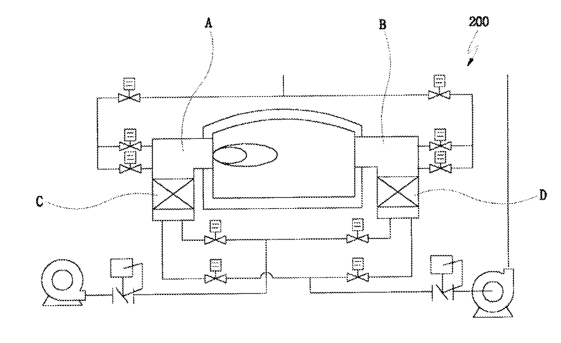
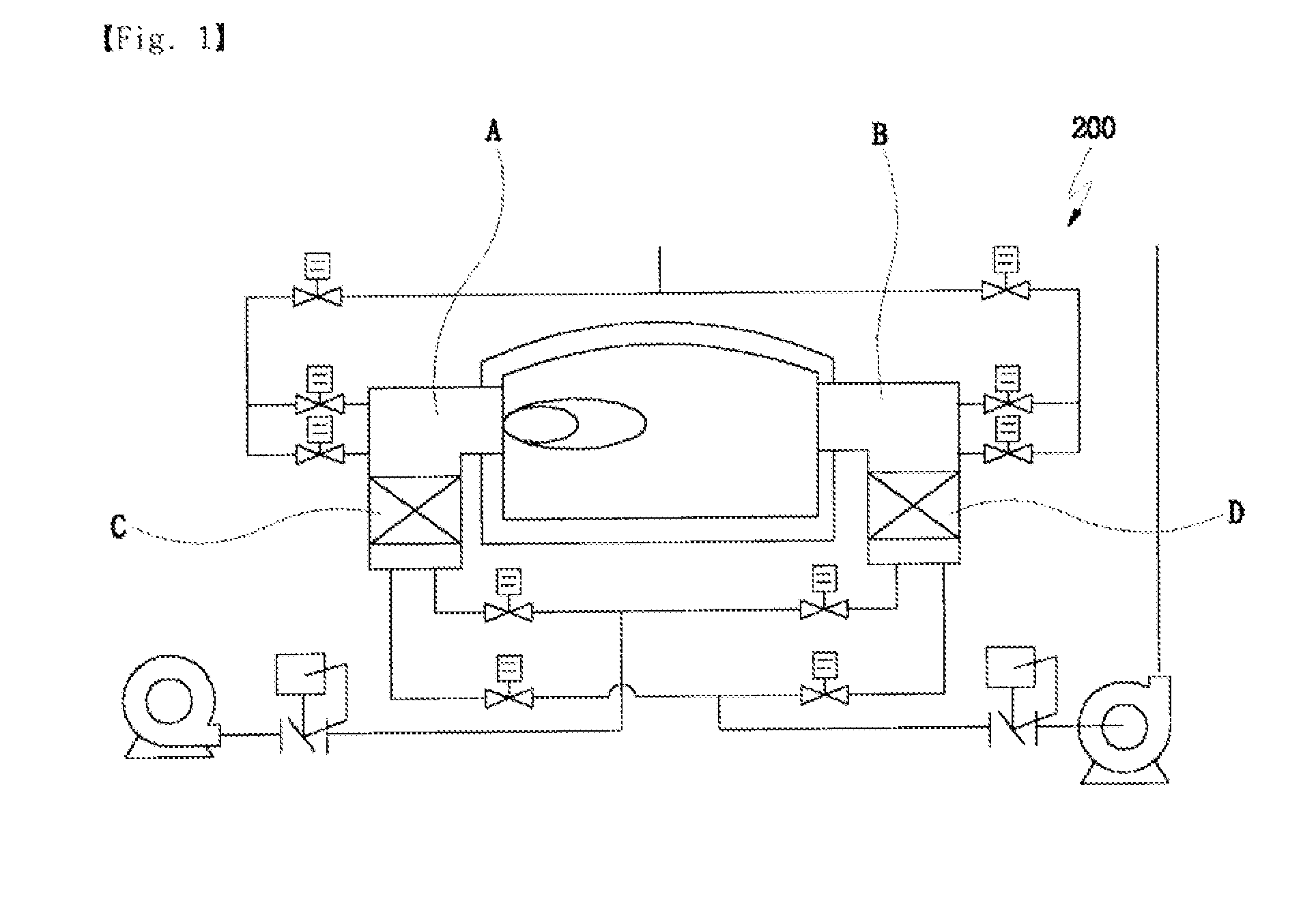
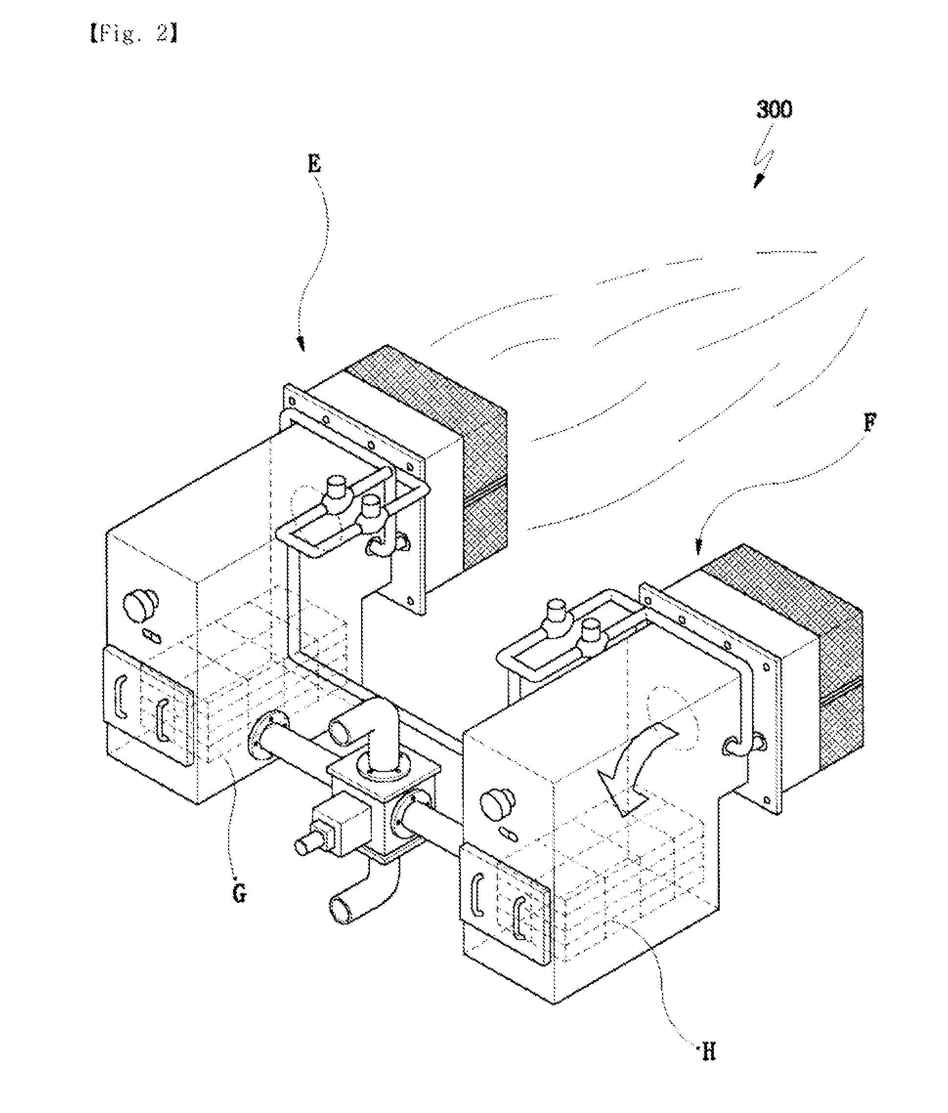
[0059]The present invention proposes to solve the problem in the related art. It is an object of the present invention to provide a full time regenerative type single radiant tube burner that can be compactly designed by a configuration that an intake and exhaust switching device having a simple structure, a regenerating unit, and a burner body are integrated
[0063]The present invention according to the above configuration can perform the full time combustion using the single radiant tube burner, thereby making it possible to maximize the combustion efficiency and improve the energy efficiency.
[0064]In addition, the present invention makes the structure of the intake and exhaust switching device simple, can compactly design the burner by mounting the regenerating unit, which is integrated with the intake and exhaust switching device, to surround the circumference of the burner body, and can manufacture the burner at a small size, such that it can be applied to various environments without limiting the installation space.

Problems solved by technology

However, these are ideal challenges and are still not completely solved.
In other words, the combustor in the related art excessively emits the amount of NOx (nitrogen oxide) upon combusting, which is a level of a risk that is harmful to an environment or a human body.
However, it is not easy to develop the energy saving type low NOx (nitrogen oxide) combustor that has the stabilization of flame, does not almost generate the unburned carbon, and has the industrial furnace system of high heat efficiency.
As a result, the method makes the air distribution uneven to avoid the peak value the generation of the NOx (nitrogen oxide).
However, when the method is applied to the combustor or the burner, etc., there is still the problem of the improvement of heat efficiency.
Further, the industrial furnace, which does not perform the existing regeneration, is partitioned into a high-temperature area and a low-temperature area when flame is emitted from the burner.
However, the regenerative combustor necessarily needs two combustors and therefore, the manufacturing cost thereof is increased.
The combustor less than 1000 KW, which has a small combustion amount, is difficult to apply since the application cost of the system is greatly increased as compared with combustion amount
In addition, it is difficult to install the burner in the combustion furnace having a narrow installation space.
In other words, it is difficult to apply to a heat treatment furnace or a chemical reaction furnace such as a carburizing furnace that the maximum size and number of the burner are limited.

Method used


Image

  • Full time regenerative type single radiant tube burner
  • Full time regenerative type single radiant tube burner
  • Full time regenerative type single radiant tube burner

Examples


Embodiment Construction

[0073]Hereinafter, a preferred embodiment of the present invention is described in detail with reference to the accompanying drawings.

[0074]FIG. 4 is a cross-sectional view showing an entire structure of a full time regenerative type single radiant tube burner of the present invention, FIG. 5 is an enlarged view of main parts of the burner structure of FIG. 4, FIG. 6 is an enlarged side cross-sectional view of main parts of an intake process of an intake and exhaust switching device according to the present invention, and FIG. 8 is an enlarged front view of main parts showing an exhaust process of the intake and exhaust switching process according to the present invention.

[0075]As shown in the drawings, the full time regenerative type single radiant tube burner of the present invention includes a radiant tube type burner 100, a regenerating unit 200 that regenerates the exhaust gas heat generated from the burner 100 and is used for preheating the intake combustion air, and an intake...


PUM


Abstract

The present invention relates to a full time regenerative type single radiant tube burner. The full time regenerative type single radiant tube burner includes a radiant tube type burner; a regenerating unit that regenerates exhaust gas heat generated from the burner and is used for preheating the intake combustion air; and an intake and exhaust switching device that passes the intake air and the exhaust gas to the regenerating unit and heat-exchanges them and simultaneously progresses the intake and exhaust processes of the burner to perform the full time combustion.The present invention according to the above configuration operation can perform the full time combustion using the single radiant tube burner to maximize the combustion efficiency, thereby improve the energy efficiency, while the present invention makes the structure of the intake and exhaust switching device 300 simple, can compactly design the burner by mounting the regenerating unit 200, which is integrated with the intake and exhaust switching device, to surround the circumference of the burner body 110 and can manufacture the burner at a small size, such that it can be applied to various environments without limiting the installation space.

Description

BACKGROUND OF THE INVENTION[0001]1. Field of the Invention[0002]The present invention relates to a single radiant tube burner, and more specifically, to a full time regenerative type single radiant tube burner.[0003]2. Description of the Related Art[0004]Generally, a combustor such as a burner, etc., is a device that combusts fuel and air that are injected at an appropriate mixing ratio, transfers heat energy generated upon combusting to other media to melt the media or change the temperature of the media, and is used to convert heat energy into electric or kinetic energy.[0005]The combustor or the burner, etc., should implement combustion reaction in an industrial furnace and the optimization of electro thermal characteristic and achieve the optimal temperature in the industrial furnace.[0006]In addition, the ideal combustor or burner, etc., should be easy to handle and be safe, be in a work environment that is harmless to a person, and be maintained at high efficiency while minimi...

Claims


Application Information

Patent Timeline
Patent Type & Authority Applications(United States)
IPC IPC(8): F24C3/04
CPCF23C3/002F24D5/08F23D14/66Y02E20/34F23D14/08F23L15/02F23N3/06
Inventor DONG, SANG KEUNYANG, JE BOKLEE, EUN KYEONG
Owner KOREA INST OF ENERGY RES
Learn More