Dynamic braking for current source converter based drive

a converter-based drive and current source technology, applied in the direction of dynamo-electric converter control, motor/generator/converter stopper, ac motor stopper, etc., can solve the problems of regenerative current flow in the line side or input source, undesirable or unacceptable, etc., to prevent or mitigate power flow, the effect of reducing the impact/stress

Active Publication Date: 2011-03-10
ROCKWELL AUTOMATION TECH
View PDF6 Cites 44 Cited by
  • Summary
  • Abstract
  • Description
  • Claims
  • Application Information

AI Technical Summary

Benefits of technology

[0005]In accordance with an aspect of the disclosure, a CSC motor drive is provided, which includes an active rectifier, an intermediate circuit with a DC link choke, an inverter driving a motor load, and a dynamic braking circuit coupled with the rectifier output and the intermediate circuit. A switching control system provides switching control signals in a first mode for normal motor drive operation and in a second mode for dynamic braking operation. In normal operation, the rectifier controls the amount of current provided to the DC link in accordance with a desired value set by the inverter needs. In the second mode, the dynamic braking circuit is engaged by selectively controlling the switched coupling of one or more braking resistors into the DC link circuit, for instanc

Problems solved by technology

For CSC drives, inherent regenerative braking capability causes regenerative current flow in the line side or inp

Method used


Image

  • Dynamic braking for current source converter based drive
  • Dynamic braking for current source converter based drive
  • Dynamic braking for current source converter based drive

Examples


Embodiment Construction

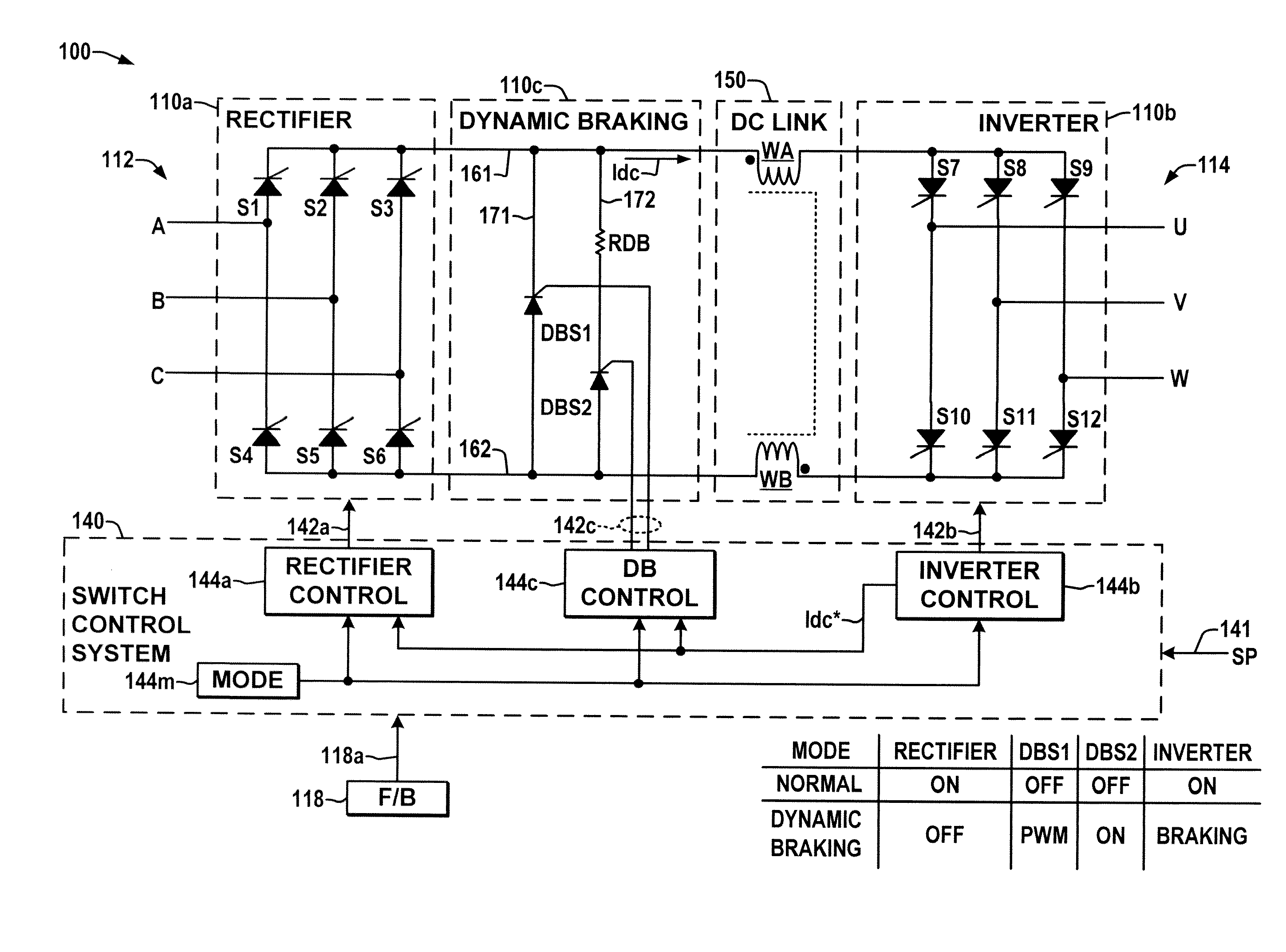
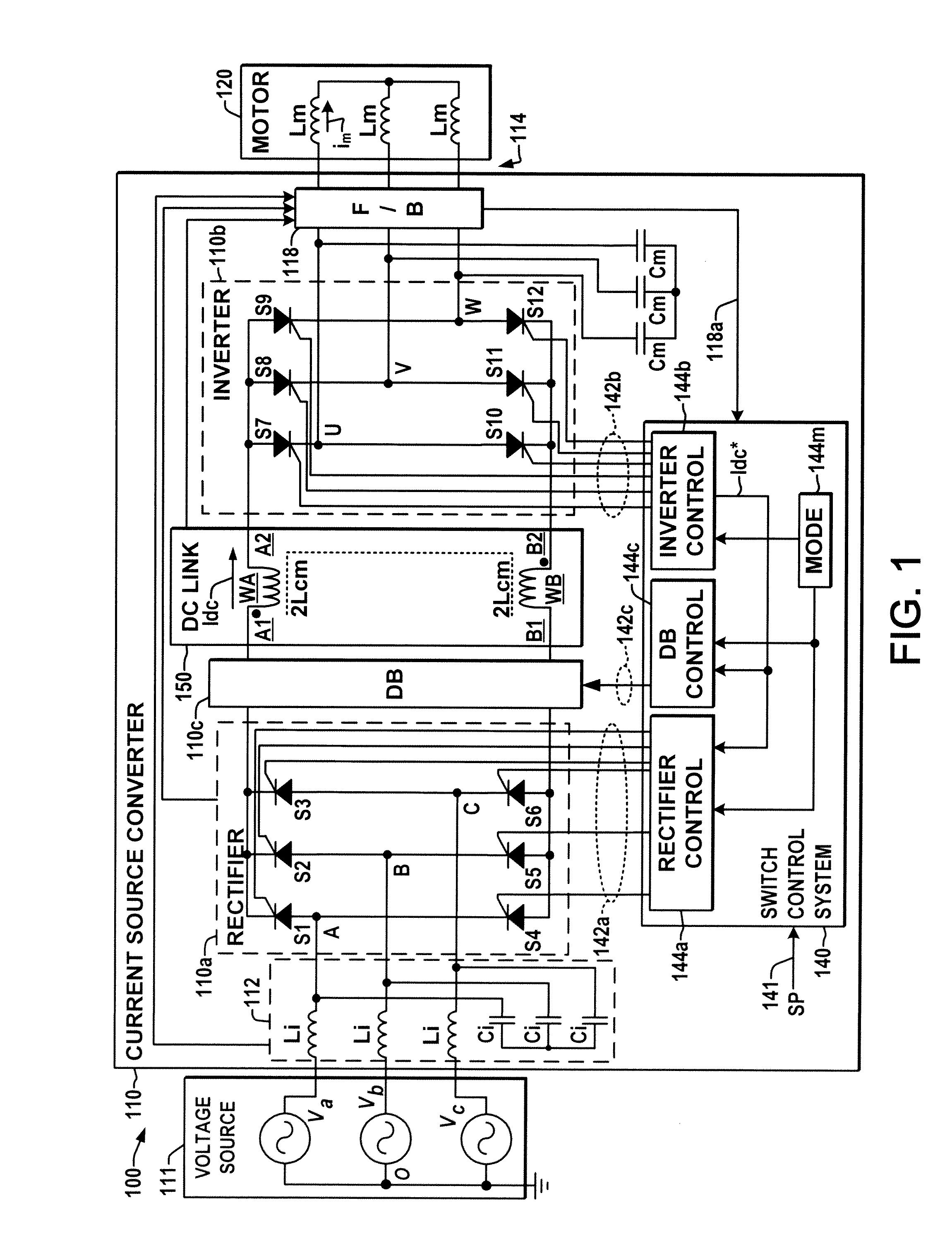
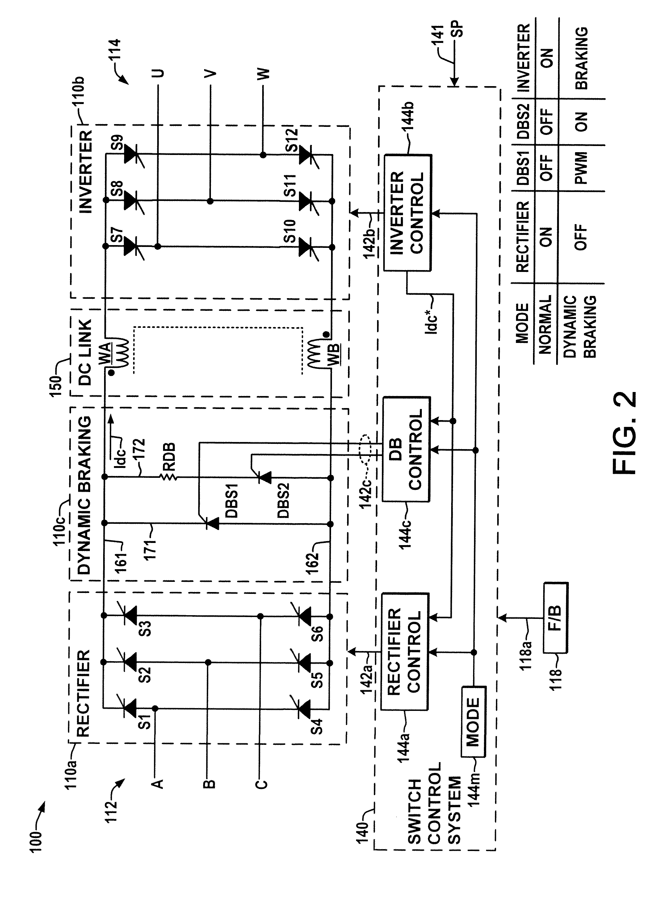
[0016]Referring now to the figures, several embodiments or implementations are hereinafter described in conjunction with the drawings, wherein like reference numerals are used to refer to like elements throughout, and wherein the various features are not necessarily drawn to scale. A system 100 is shown in FIG. 1, including an exemplary three-phase AC voltage source 111 providing input power to a motor drive 110 that converts the input power to drive a motor load 120 coupled to a converter output 114. The drive 110 is a current source converter (CSC) type, with an input 112 connected to the AC power source 111. While illustrated as having a three phase input 112, other embodiments may provide a single phase AC input or may include a multiphase input adapted to receive three or more input phases. The CSC drive 110 provides variable frequency, variable amplitude single or multiphase AC output power at output terminals 114 to drive an AC motor load 120, which has three phase windings i...


PUM


Abstract

Current source converter (CSC) based motor drives and control techniques are presented in which DC link current is regulated to a level set by the output inverter during dynamic braking operation by pulse width modulation of a braking resistance connection signal to maintain control of motor torque and speed while mitigating or preventing line side regenerative currents.

Description

REFERENCE TO RELATED APPLICATION[0001]This application claims priority to and the benefit of U.S. Provisional Patent Application Ser. No. 61 / 239,937, filed Sep. 4, 2009, entitled“DYNAMIC BRAKING FOR CURRENT SOURCE CONVERTER BASED DRIVE”, the entirety of which is hereby incorporated by reference.FIELD OF THE INVENTION[0002]The present invention relates generally to electrical power conversion and more particularly to dynamic braking for current source converter-based drive systems.BACKGROUND OF THE INVENTION[0003]Motor drives are electric power conversion systems that convert input power from a line-side source to a different form to provide controlled drive currents to the windings of an electric motor. Current source converter (CSC) type drives typically include a switching rectifier with AC input power being selectively switched to create a DC link current that is fed to an output inverter which creates single or multi-phase AC output current for driving a motor load at a controll...

Claims


Application Information

Patent Timeline
IPC IPC(8): H02P3/22
CPCH02P27/08H02P3/18B60L7/06B60L9/28B60L2210/30B60L2210/44B60L2240/421B60L2240/423B60L2240/529B60L2240/527Y02T10/64Y02T10/72
Inventor RINEH, GHODRATOLLAH ESMAEILINAM, SANG WOOPANDE, MANISHCHENG, ZHONGYUAN
Owner ROCKWELL AUTOMATION TECH
Why Eureka
Try Eureka