
Semiconductor device having plural semiconductor chips laminated to each other

a semiconductor chip and semiconductor technology, applied in semiconductor devices, semiconductor/solid-state device details, instruments, etc., can solve the problems of increasing the chip area, affecting the performance of the entire chip, so as to reduce the chip area of the second semiconductor chip

Active Publication Date: 2011-03-10
LONGITUDE LICENSING LTD
View PDF5 Cites 39 Cited by
  • Summary
  • Abstract
  • Description
  • Claims
  • Application Information

AI Technical Summary

Benefits of technology

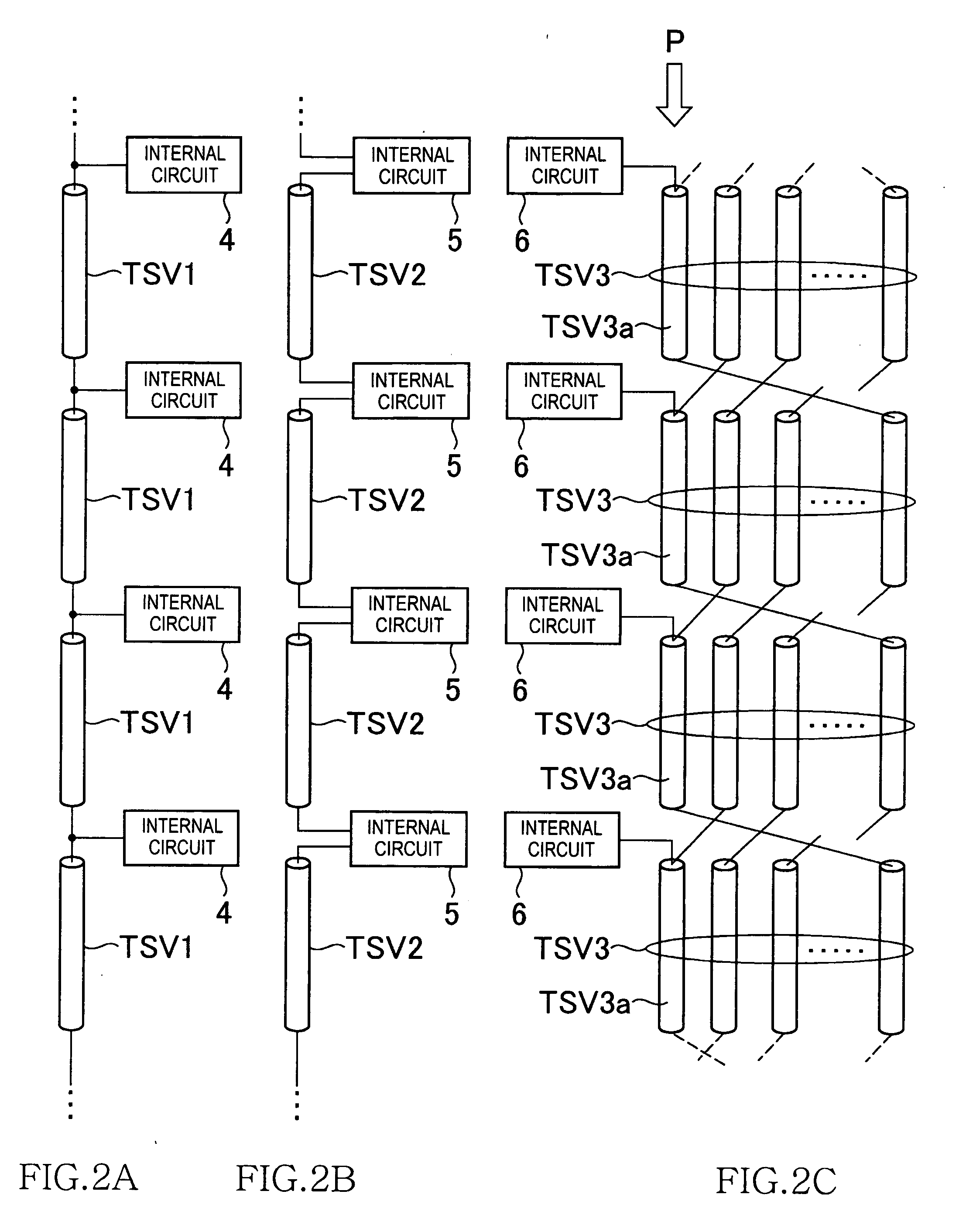
The patent text describes a semiconductor device with multiple semiconductor chips that are connected to each other through through silicon vias (penetration electrodes). The first semiconductor chip stores information about which through silicon vias to use for data transfer, and it sends this information to the second semiconductor chip. This invention eliminates the need for a circuit to store the through silicon via switching information in a nonvolatile manner, reducing the chip area of the second semiconductor chip.

Problems solved by technology

However, the entire chip becomes defective when even one of the through silicon vias becomes defective, and if a plurality of the chips are stacked, all the chips become defective.
However, when a circuit is provided in each of the semiconductor chips for storing the through silicon via switching information in a nonvolatile manner, it can lead to an increase in the chip area.
This problem is not limited to semiconductor memory devices such as stacked DRAMs, but can occur to all stacked semiconductor devices in which a plurality of semiconductor chips are stacked and electrically connected to each other via through silicon vias.

Method used


Image

  • Semiconductor device having plural semiconductor chips laminated to each other
  • Semiconductor device having plural semiconductor chips laminated to each other
  • Semiconductor device having plural semiconductor chips laminated to each other

Examples


Embodiment Construction

[0023]Preferred embodiments of the present invention will be explained below in detail with reference to the accompanying drawings.

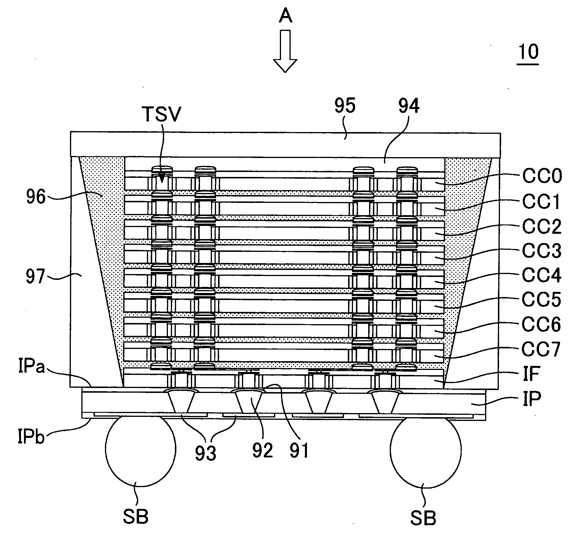
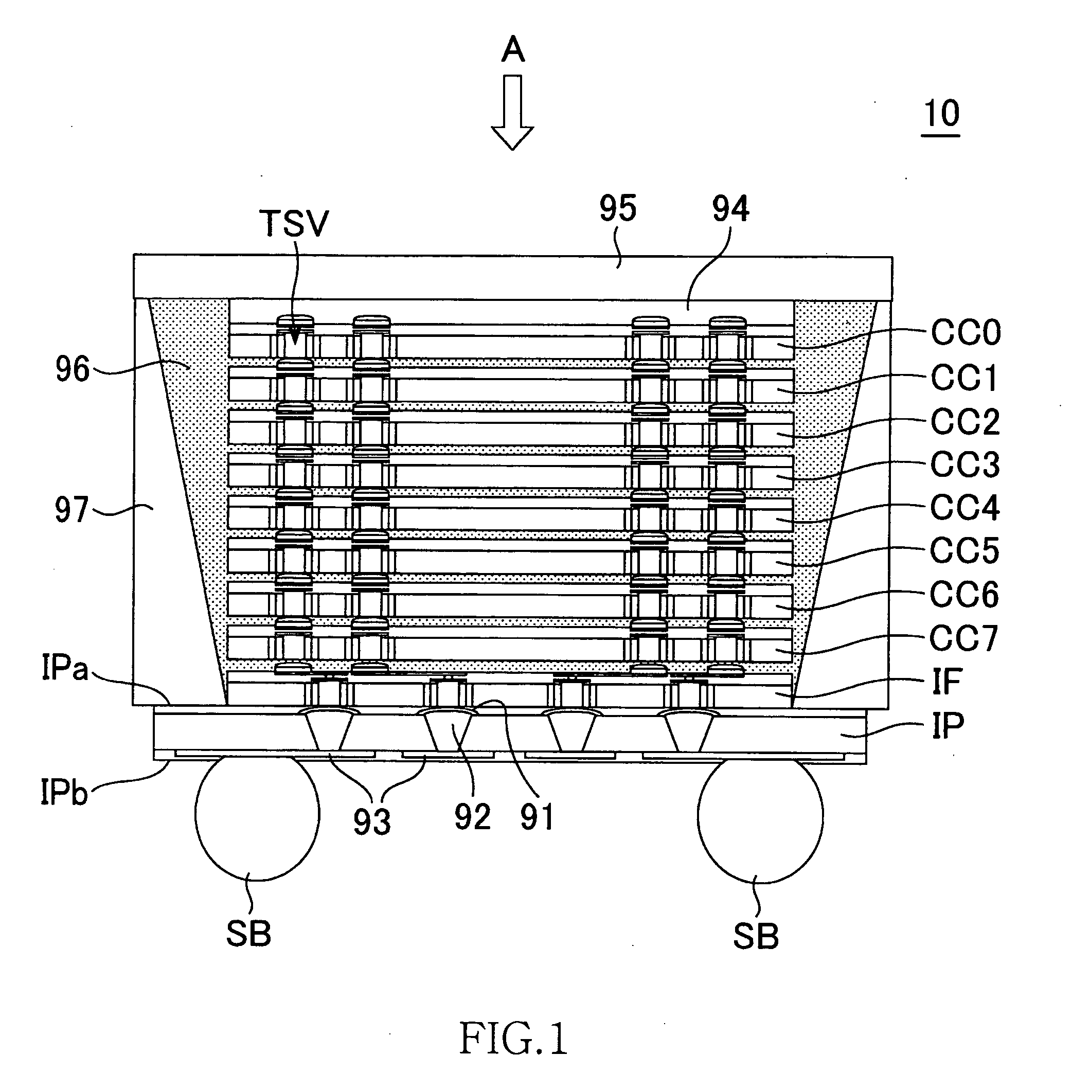
[0024]FIG. 1 is a schematic cross-sectional view provided to explain the structure of a semiconductor memory device 10 according to the preferred embodiment of the present invention.

[0025]As shown in FIG. 1, the semiconductor memory device 10 according to this embodiment has the structure where 8 core chips CC0 to CC7 that have the same function and structure and are manufactured using the same photo mask set, an interface chip IF that is manufactured using a photo mask set different from that of the core chips and an interposer IP are laminated. The core chips CC0 to CC7 and the interface chip IF are semiconductor chips using a silicon substrate and are electrically connected to adjacent chips in a vertical direction through plural through silicon vias TSV penetrating the silicon substrate. Meanwhile, the interposer IP is a circuit board that is made of...


PUM


Abstract

In a stacked semiconductor device in which a plurality of through silicon vias used for data transfer are shared among a plurality of semiconductor chips, a first semiconductor chip included in the semiconductor chips holds through silicon via switching information for specifying a through silicon via among the through silicon vias to be used for data transfer, and transfers the through silicon via switching information to a second semiconductor chip included in the semiconductor chips. According to the present invention, because the through silicon via switching information is transferred from the first semiconductor chip to the second semiconductor chip, a circuit for storing the through silicon via switching information in a nonvolatile manner is not required in the second semiconductor chip. With this arrangement, a chip area of the second semiconductor chip can be reduced.

Description

BACKGROUND OF THE INVENTION[0001]1. Field of the Invention[0002]The present invention relates to a stacked semiconductor device, and more particularly relates to a stacked semiconductor device including a plurality of semiconductor chips electrically connected by through silicon vias.[0003]2. Description of Related Art[0004]A memory capacity required in semiconductor memory devices such as DRAM (Dynamic Random Access Memory) is increasing every year. In recent years, there has been proposed a method to meet this requirement. In this method, a plurality of memory chips are stacked and electrically connected via through silicon vias arranged on a silicon substrate (see Japanese Patent Application Laid-open No. 2007-158237).[0005]Specifically, in a semiconductor memory device in which an interface chip having front end units such as interface circuits incorporated thereon and a core chip having back end units such as memory cores incorporated thereon are stacked, because read data that...

Claims


Application Information

Patent Timeline
Patent Type & Authority Applications(United States)
IPC IPC(8): H03M9/00H01L23/48H01L25/00
CPCG11C5/02H01L23/3128H01L2924/0002H01L2924/13091H01L2224/0401H01L23/3135H01L24/05H01L24/06H01L24/16H01L25/0657H01L2224/05096H01L2224/05567H01L2224/16145H01L2224/73253H01L2225/06513H01L2225/06517H01L2225/06541H01L2924/15311H01L2924/3011H01L2924/01037H01L2924/01055H01L2224/05552H01L2924/00H01L23/481
Inventor IDE, AKIRATAKISHITA, RYUJI
Owner LONGITUDE LICENSING LTD
Learn More