Blood volume measuring method and blood volume measuring apparatus

a blood volume and measuring method technology, applied in the direction of instruments, catheters, angiography, etc., can solve the problems of sensitive method to artifacts, high cost, and often interrupted measurement of blood pressure waveforms, and achieve accurate removal of artifacts and high resolution

Active Publication Date: 2011-03-10
NIHON KOHDEN CORP
View PDF11 Cites 25 Cited by
  • Summary
  • Abstract
  • Description
  • Claims
  • Application Information

AI Technical Summary

Benefits of technology

[0030]It is therefore an object of the invention to provide a method, apparatus and program of removing an artifact which, in an apparatus for analyzing respiratory variation of the stroke volume of the patient in order to determine the fluid response of the patient or adequately set artificial ventilation, can accurately remove an artifact without requiring an expensive A / D converter having a high resolution.

Problems solved by technology

Since an ECG and a pulse oximetry plethysmogram are used, there is a problem in that the method is sensitive to an artifact.
In the second method where, by using correlation between the stroke volume and the blood pressure, the pulse pressure of the blood pressure of the patient is measured to measure respiratory variation of the stroke volume, by contrast, the blood pressure is directly measured by using an arterial catheter, and hence there is a problem in that the measurement of the blood pressure waveform may be often interrupted by zero balance, flash, or the like, and the interrupted portion must be omitted from the analysis.
Therefore, there is a problem in that the method is sensitive to an artifact.

Method used


Image

  • Blood volume measuring method and blood volume measuring apparatus
  • Blood volume measuring method and blood volume measuring apparatus
  • Blood volume measuring method and blood volume measuring apparatus

Examples


Embodiment Construction

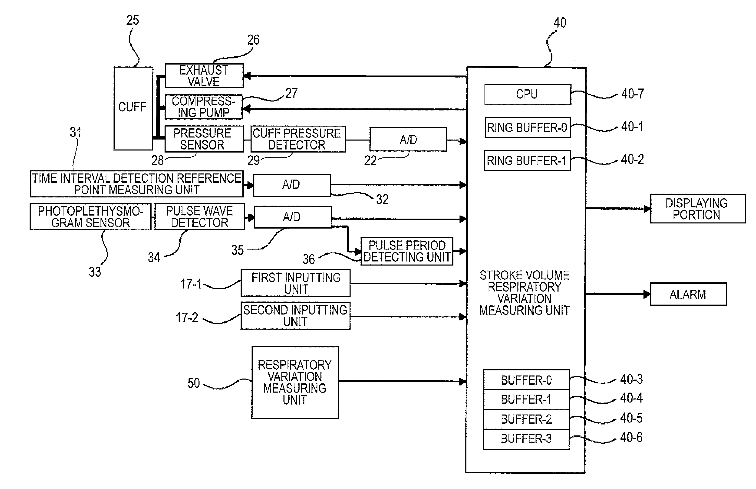
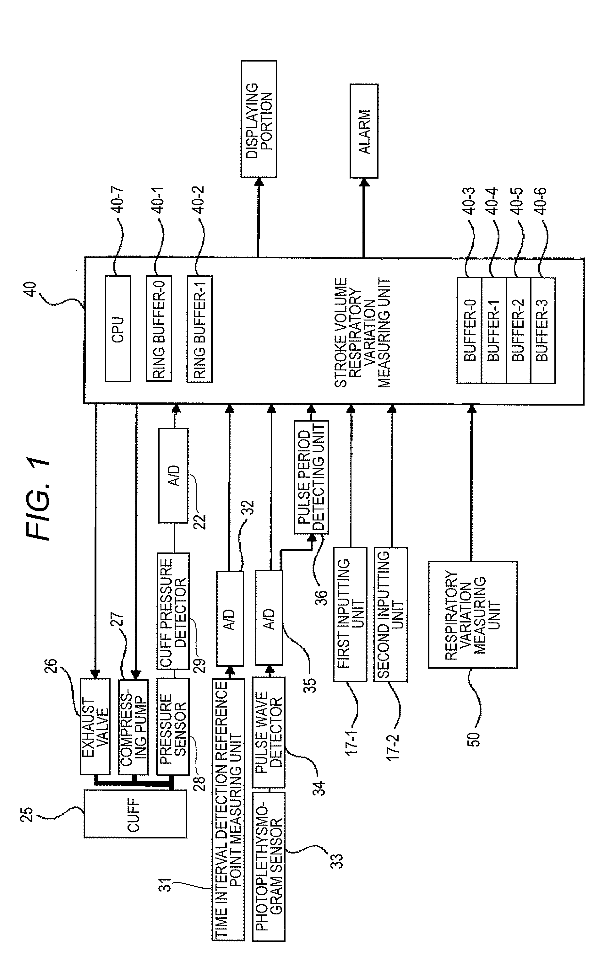
[0051]Next, an embodiment of a biological signal monitoring apparatus to which the present invention is applied will be described in detail with reference to the drawings. FIG. 1 is a block diagram illustrating the configuration of the biological signal monitoring apparatus according to the invention.

[0052]The biological signal monitoring apparatus includes a cuff 25, a compressing pump 27, a pressure sensor 28, a cuff pressure detector 29 and an A / D converter 22.

[0053]The cuff 25 is attached to an upper arm of the patient for measurement. In the cuff 25, the interior is opened or closed with respect to the atmosphere by an exhaust valve 26 installed in a body of the biological signal monitoring apparatus. Air is supplied to the cuff 25 by the compressing pump 27 installed in the body. The pressure sensor 28 is mounted in the body, and an output of the pressure sensor 28 is detected by the cuff pressure detector 29. An output of the cuff pressure detector 29 is converted into a digi...


PUM


Abstract

A blood volume measuring method includes: acquiring data of stroke volume variation at each respiratory rate, and storing the acquired data in a first buffer; reading an N1 number of the data stored in the first buffer, from the first buffer, and storing the N1 number of the data in a second buffer; excluding a part of the data stored in the second buffer, a value of each of which exceeds a first upper limit or falls below a first lower limit, from the data stored in the second buffer, and storing the other of the data stored in the second buffer, in a third buffer; acquiring a deviation of each of the data stored in the third buffer, from a median value of the data stored in the third buffer, excluding a part of the data stored in the third buffer, the deviation of each of which exceeds a second upper limit or falls below a second lower limit, from the data stored in the third buffer, and storing the other of the data stored in the third buffer, in a fourth buffer; determining whether N2 / N1 is within an allowable value or not, wherein the N2 is a number of the data stored in the fourth buffer; and when it is determined that the N2 / N1 is within the allowable value, calculating data of average stroke volume variation based on the data stored in the fourth buffer.

Description

BACKGROUND OF THE INVENTION[0001]The present invention relates to a blood volume measuring method and a blood volume measuring apparatus, particular to method, apparatus and program of removing an artifact in an apparatus for analyzing respiratory variation of the stroke volume of the patient in order to determine the fluid response of the patient or adequately set artificial ventilation.[0002]There are related-art methods of analyzing respiratory variation of the stroke volume of the patient. In a first method, the stroke volume is measured from variation of the pulse wave propagation time by using correlation between the pulse wave propagation time and the stroke volume (see JP-A-2005-312947), and respiratory variation is analyzed from the acquired stroke volume.[0003]JP-A-2005-312947 discloses the following biological signal monitoring apparatus shown in FIG. 8. FIG. 8 is a block diagram illustrating the configuration of the related-art biological signal monitoring apparatus, and...

Claims


Application Information

Patent Timeline
Patent Type & Authority Applications(United States)
IPC IPC(8): G06F19/00A61B5/021G06F17/18
CPCA61B5/02255A61B5/029A61B5/0285
Inventor SUGO, YOSHIHIROHYOGO, MITSUSHI
Owner NIHON KOHDEN CORP
Why Eureka
Try Eureka