Electron beam layer manufacturing

a technology of electron beam and layer manufacturing, applied in the direction of electron beam welding apparatus, process and machine control, program control, etc., can solve the problems of ineffective solution, potential complications of approach, and difficulty in delivering effective solutions

Active Publication Date: 2011-03-17
SCIAKY SA
View PDF66 Cites 248 Cited by
  • Summary
  • Abstract
  • Description
  • Claims
  • Application Information

AI Technical Summary

Benefits of technology

The apparatus may have associated with it a vapor protection device that comprises: a block that includes a base portion and a cover portion, the base portion including at least one fluid port that receives a gas stream that may be controllably regulated, the base portion and the cover portion each having an aperture that is generally axially aligned with each other and is adapted to be axially aligned substantially overhead of a molten metal pool deposit; at least one reflective substrate that is in optical communication with at least one of the apertures of the cover portion, or the base portion, for reflecting an image that passes through such aperture to a separately housed optical imaging device that records the image; wherein the gas stream enters the at least one fluid port and exits the block through one of the apertures, and provides an optically transparent protective barrier to prevent passage of metal vapor through the other aperture.

Problems solved by technology

This approach may pose potential for complications due to the subjectivity of the observations of the operator, due to any delay experienced between an observation and any adjustment in operating parameters, and / or due to improper selection of parameters.
However, the art has yet to provide an effective solution.
Among the difficulties encountered in attempting to implement closed loop controls for LM techniques, and especially in the area of LM that employs layer by layer build up of articles using molten metal, has been the ability to suitably monitor deposits of metal.
This is a particularly acute difficulty when attempting to conduct LM at relatively high output rates.
Optics may be susceptible to vapor build-up that occurs during manufacturing.
The amount of data and the rate at which images must be captured for analysis also has faced limitations due to camera hardware.
By way of illustration, in achieving rapid imaging, heat may be generated by operation of the associated camera electronics; this may have the effect of corrupting images that are obtained.
Overhead positioning of a camera also puts the camera at potential risk of image distortion due to pixel excitation by scattered electrons.
Also, suitably robust, commercially practical, and compact designs for use, especially in LM, have been unavailable.

Method used


Image

  • Electron beam layer manufacturing
  • Electron beam layer manufacturing
  • Electron beam layer manufacturing

Examples


Embodiment Construction

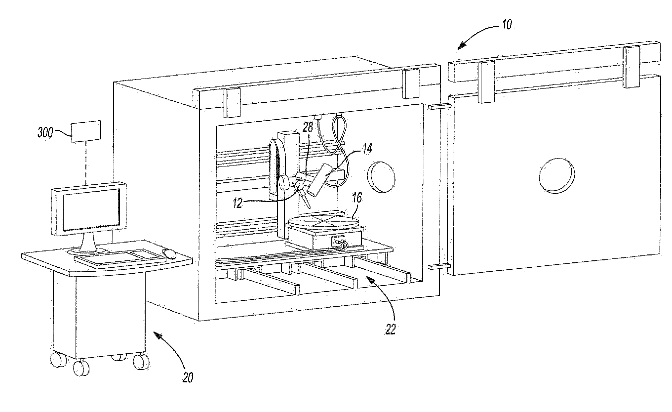
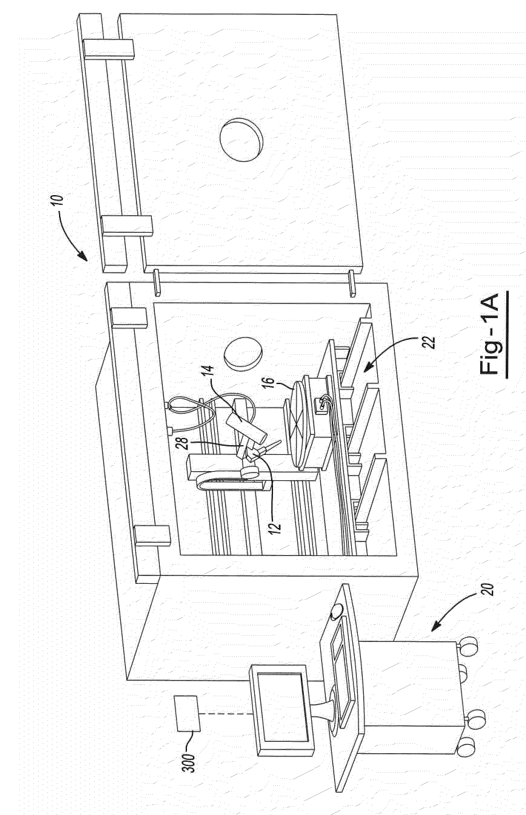
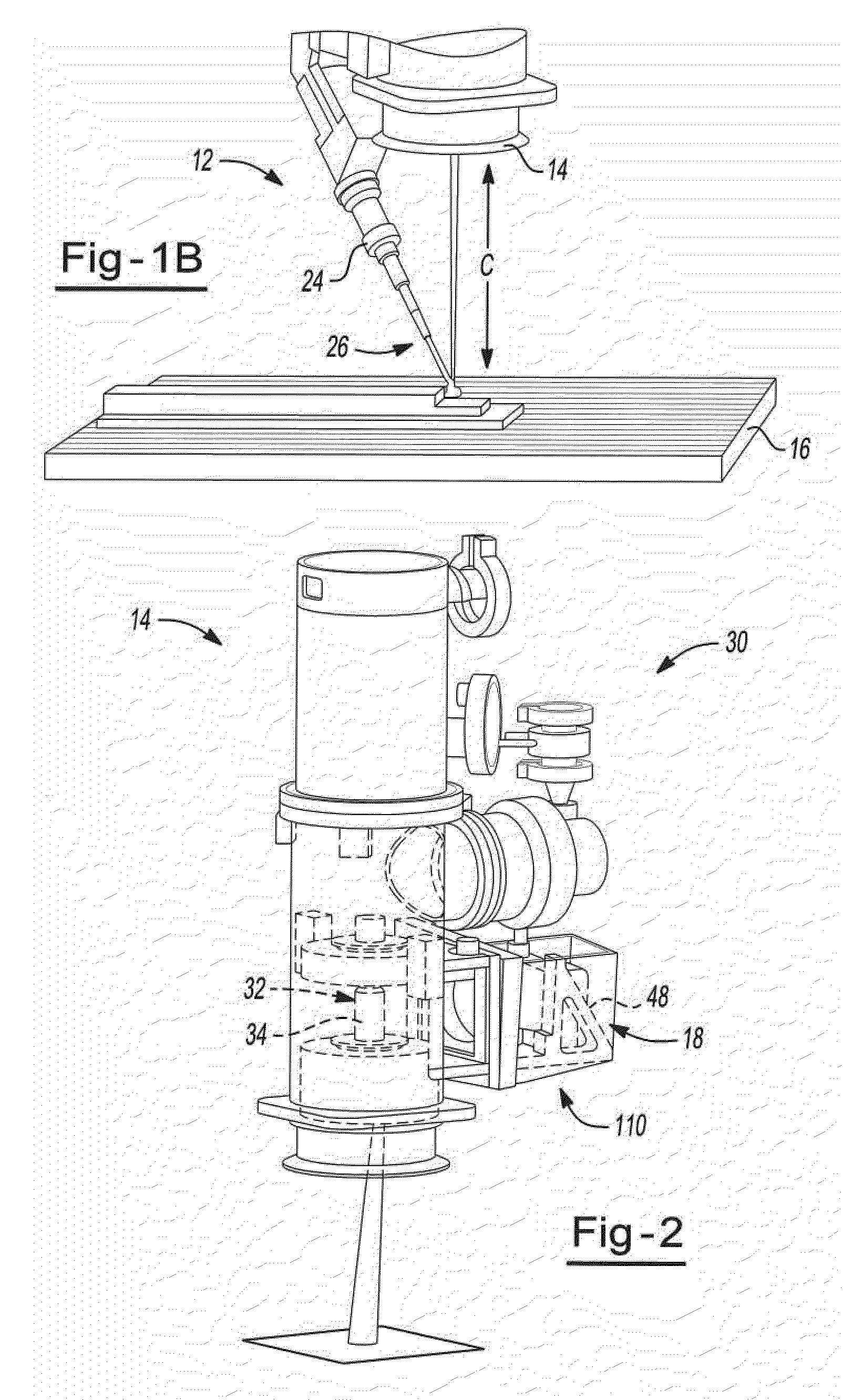
The present invention provides an apparatus and process for layer manufacturing (LM) of a three-dimensional article. The invention is particularly directed at an apparatus and process for LM that provides high output rates. For example, it is possible that article (e.g., metallic article) build rates of at least about 0.5, 1.0, 1.5, 2.5, 3.5, or even 4.0 cm3 / hr, or higher, may be employed. It is also possible that, article (e.g., metallic article) build rates of at least about 2.5, 3.0, 3.3, 5, or even 6.8 kg / hour (e.g. having an average bead width of about 10 to about 15 mm) may be employed.

In general, the apparatus may include combinations of at least two or more of a material delivery device (e.g. a wire feed device); an energy emission device that applies energy to liquefy a material (e.g., a metal) delivered by the material delivery device; a work piece support onto which liquefied material is deposited; a closed loop control device (e.g., one that is in signaling communication...


PUM

PropertyMeasurementUnit
widthaaaaaaaaaa
widthaaaaaaaaaa
widthaaaaaaaaaa

Abstract

A process and apparatus for free form fabrication of a three-dimensional work piece comprising (a) feeding raw material in a solid state to a first predetermined location; (b) depositing the raw material onto a substrate as a molten pool deposit under a first processing condition; (c) monitoring the molten pool deposit for a preselected condition; (d) comparing information about the preselected condition of the monitored molten pool deposit with a predetermined desired value for the preselected condition of the monitored molten pool deposit; (e) solidifying the molten pool deposit; (f) automatically altering the first processing condition to a different processing condition based upon information obtained from the comparing step (d); and repeating steps (a) through (f) at one or more second locations for building up layer by layer a three-dimensional work piece. The apparatus is characterized by a detector that monitors a preselected condition of the deposited material and a closed loop electronic control device for controlling operation of one or more components of the apparatus in response to a detected condition by the detector.

Description

FIELD OF THE INVENTIONThe present invention relates generally to layer manufacturing or fabrication of articles and, more specifically, to additive manufacturing or solid freeform fabrication of articles using electron beam energy and closed loop control technology.BACKGROUND OF THE INVENTIONFree form fabrication (FFF) and additive manufacturing (AM) are names for a general class of layer manufacturing (LM), in which a three-dimensional (3-D) article is made by the sequential build-up of layers of material. Prior to physically building up the article, the process often begins with creating a computer aided design (CAD) file to represent the image or drawing of a desired article. Using a computer, information about this article image file is extracted, such as by identifying information corresponding to individual layers of the article. Thus, to derive data needed to form an article by LM, conceptually the article is sliced into a large number of thin layers with the contours of each...

Claims


Application Information

Patent Timeline
Patent Type & Authority Applications(United States)
IPC IPC(8): C23C4/06
CPCB22F3/1055B22F2998/00G05B15/02B23K15/0046B22F2003/1057B22F3/003B22F2999/00B33Y40/00B33Y30/00B33Y50/02B22F10/25B23K15/0086B22F10/368B22F10/366B22F12/41B22F12/90B23K15/0013B23K15/0093B23K15/02B23K15/06B23K2103/14B22F12/70B22F12/22B22F10/32B22F12/38B22F10/36B22F2203/03Y02P10/25B33Y10/00G05B19/4099G05B2219/35134G05B2219/49007
Inventor STECKER, SCOTT
Owner SCIAKY SA
Why Eureka
Try Eureka