Low profile solar tracking systems & methods

a solar tracking system and low-profile technology, applied in the field of solar energy collection, can solve the problems of reducing the overall efficiency of the system, affecting the daily and/or seasonal positions of the solar array, and the maintenance of any one panel in the array can be problematic, so as to efficiently track the daily and/or seasonal positions, and efficiently collect solar power

Active Publication Date: 2011-03-17
PIZZARELLO GUY A +1
View PDF49 Cites 31 Cited by
  • Summary
  • Abstract
  • Description
  • Claims
  • Application Information

AI Technical Summary

Benefits of technology

[0006]The present invention is a system for providing solar energy collection with a modular design or array of solar energy collection devices or panels angled to the position of the sun. The solar collection systems devised in the present invention have either a combination of fixed panels and tracking panels or only tracking panels, both kinds of panels converting sunlight incident upon them to electrical power. The tracking panels of the present invention follow the daily movement of the sun to efficiently collect solar power from dawn to dusk. The present invention includes systems for providing both single axis and dual axis solar tracking. The first axis of the system is used to track solar daily changes, the tracking panels adding power to the system when the sun is moving through zenith between approximately 10 AM to 2 PM. The shadowing of the tracking panels is minimal to zero at noon. The second axis of the system is used to adjust to solar seasonal changes by inclining the solar panel module or system to the appropriate angle. Both axes are driven by motors that are controlled by hardware and programmable software that seeks optimum angular positions both daily and seasonally. The system and software is designed to account for in site installation at any latitude to efficiently track the daily and / or seasonal positions. The present systems in general are also designed to be sufficiently rugged to withstand forces of the elements such as wind, rain, etc., and to meet international and national building code specifications. In addition, the physical structure of the system is designed for ease of installation and maintenance because of its modular design. Such modular design of the solar panels of the present invention allows connections to adjacent modules or arrays on a variety of sites such as residential roof tops, factory rooftops, large ground installations, on patio covers, car ports, parking lot shade structures etc.

Problems solved by technology

A disadvantage of the stationary flush mount configuration is that the panels are not optimally orientated to the position of the sun, other than when the sun is normal or perpendicular to the panel surface, thereby reducing the overall efficiency of the system.
Another disadvantage of this configuration is that when the panels are configured contiguously in a large array, maintenance of any one panel in the array can be problematic.
In most cases, each panel is rigidly attached to its underlying roof attachment structure and may not be easily removed.
In these cases, maintenance personnel are forced to walk on top of the glass covered solar panels, thereby risking damage to each panel traversed.
A disadvantage of such tracking configurations is that, due to shading, adjacent rows of panels are typically not mounted contiguous to one another, but, rather, are separated by an optimal distance.
The separation of adjacent rows results in a poorer utilization of rooftop area and, in turn, reduces the overall efficiency of the system.
Another disadvantage of many single and dual axis trackers is that, because the tracker rotates each panel about its longitudinal axis, the standoff height of the panels must be high enough such that when rotated to their extreme, the panel does not contact the dwelling.
This increased standoff height presents higher bending moment loads onto the roof attachment structure in the presence of wind forces and is aesthetically undesirable, especially on sloped rooflines which may not have a parapet.

Method used


Image

  • Low profile solar tracking systems & methods
  • Low profile solar tracking systems & methods
  • Low profile solar tracking systems & methods

Examples


Embodiment Construction

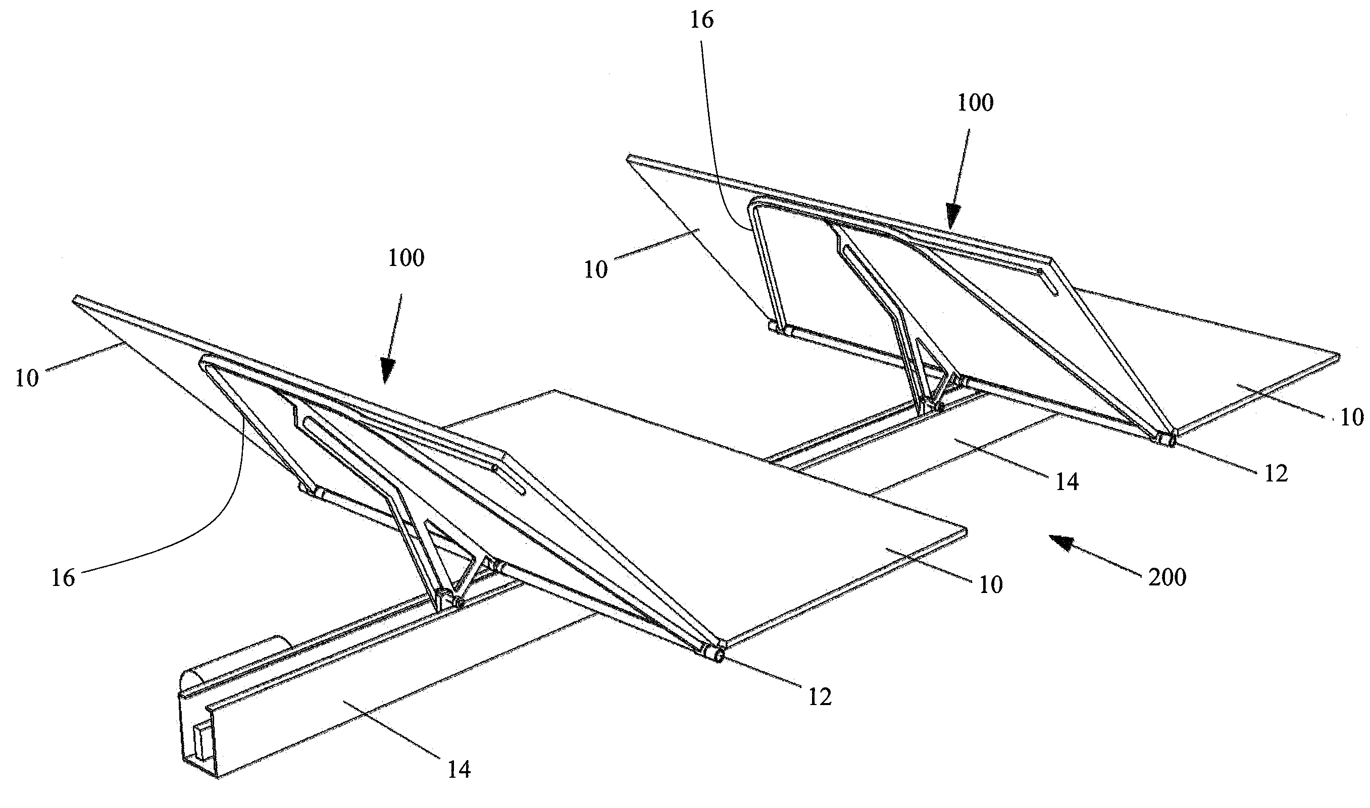
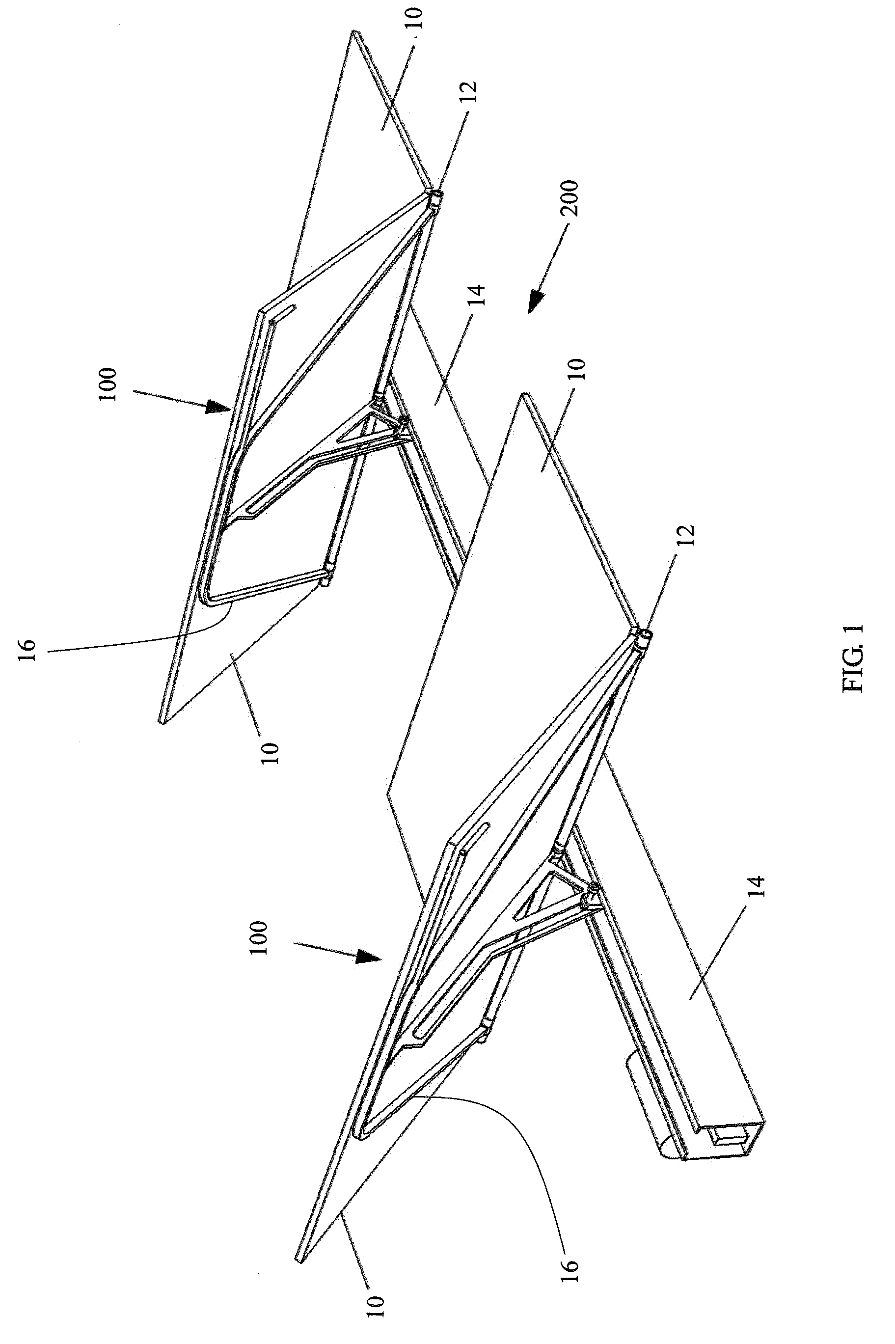
[0039]Referring now more particularly to the drawings, FIG. 1 shows a perspective view of a tracking assembly 200, which is comprised of one or more tracking units 100. In this particular figure, only two tracking units are shown for clarity. In this embodiment, each tracking unit 100 has two solar panels 10 and provides a hinge shaft 12 shared between two substantially identical and adjacent solar panels 10. In a tracking assembly 200, the tracking units 100 share a common structural channel frame 14.

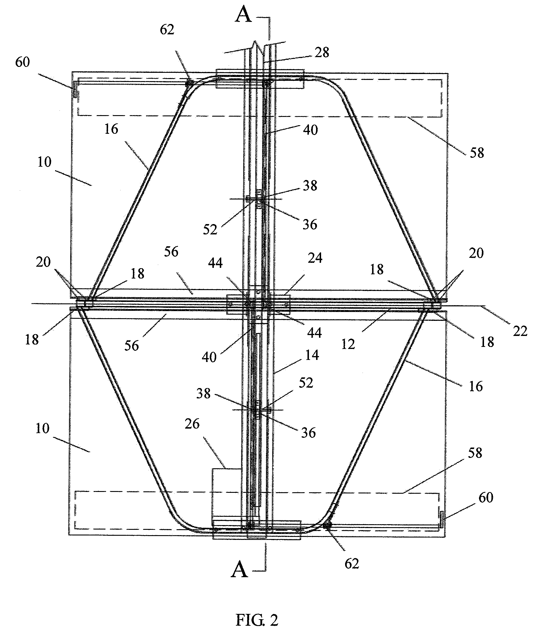
[0040]FIG. 2 shows a plan view of the method of attachment of solar panels 10 to the tracking unit. The underside of each solar panel 10 rests on a respective panel frame 16 and is secured using panel clips 18. Each end of each panel frame 16 is connected to a hinge collar 20, which rotates about the fixed hinge shaft 12. The centerline of the hinge shaft 12 defines the hinge daily axis 22, and is the axis of rotation for the solar panel 10. Frame mounting bracket 24 is used to secure ...


PUM


Abstract

A solar energy collection system comprises a frame for mounting the system on a suitable substrate and a plurality of solar panels disposed adjacent to one another on the frame. A first set of the solar panels are movable relative to a second set of the solar panels, for tracking movement of the sun during the day. Solar panels of the first set are arranged in alternating fashion with solar panels of the second set. In some embodiments of the invention, the panels in the second set of solar panels are stationary. The second set of solar panels, in some embodiments, are disposed substantially flat, relative to the frame and the substrate on which the frame is mounted. In some embodiments, differing from those in which the second set of solar panels are stationary, the second set of solar panels may be arranged to be movable relative to the first set of solar panels.

Description

CROSS-REFERENCE TO RELATED APPLICATIONS[0001]This application claims the benefit under 35 U.S.C. 119(e) of the filing date of Provisional U.S. Application Ser. No. 61 / 272,965, filed on Nov. 24, 2009, and expressly incorporated herein by reference, in its entirety.BACKGROUND OF THE INVENTION[0002]The present invention is in the technical field of collecting solar energy. More particularly, the present invention is in the technical field of systems that provide an infrastructure for the mounting of solar energy collection devices to the rooftop of a commercial structure\dwelling such that the solar energy collection devices are optimally orientated to the radiation emitted by the sun, as it traverses the sky, from sunrise to sunset. The tracker assembly may also be implemented on patio covers, car ports, parking lot shade structures, and the like.[0003]Prior practice, with respect to the attachment of solar energy collection devices to commercial structures\dwellings, such as photovol...

Claims


Application Information

Patent Timeline
Patent Type & Authority Applications(United States)
IPC IPC(8): F24J2/40F24J2/38F24J2/00F24S23/70F24S50/20
CPCY02B10/20Y02E10/47F24J2/5424F24J2/541F24J2/5233F24S25/13F24S30/425F24S30/455F24S2030/16H02S20/32Y02E10/52H02S30/10H02S40/22
Inventor PIZZARELLO, GUY A.NOLLER, LANCE S.
Owner PIZZARELLO GUY A
Why Eureka
Try Eureka