Method and machine for machining parts using spark-erosion milling

a technology of spark-erosion milling and parts, which is applied in the direction of electrical-based machining apparatus, program control, instruments, etc., can solve the problems of increasing the need to perform considerably greater movements, and the need to rapidly increase the separation of the tool from the part, so as to eliminate the displacement instabilities of the tool electrode

Inactive Publication Date: 2011-03-17
AGIE CHARMILLES +1
View PDF14 Cites 7 Cited by
  • Summary
  • Abstract
  • Description
  • Claims
  • Application Information

AI Technical Summary

Benefits of technology

[0034]In these conditions, when the direction of the trajectory segments changes, it is simple to determine that the regulation movements are being performed at a certain angle relative to the trajectory as far as the end of the current segment and change direction on crossing a boundary defined by the bisecting line with the next segment. At this point, it is thus possible to avoid requiring the tool electrode to change position abruptly causing a collision that would be fatal for the tool.
[0035]The elementary regulation movements remain oriented most of the time at the same angle relative to the trajectory, but a chan

Problems solved by technology

When machining parts using this method, because of the relatively high speeds of advance, there is a permanent risk of short circuits which stop the machining and can cause an abrupt collision between the tool and the part.
When such a risk occurs, the tool must rapidly increase its separation from the part, more precisely widen its spark gap.
The drawback in these working conditions however consists in that, to obtain a sufficient modification of the width of the gap, it will be necessary to perform considerably greater movements by moving backward on the predetermined tool path.
Such movements of large amplitude cannot be performed fast enough because of the inertia of the elements of the machine tool supporting the tool; furthermore, in finishing operations, the width of the gap is not substantially modified by movements in the direction of advance on the main trajectory, considerably reducing the effectiveness of these movements.
The patent EP 0 555 818 discloses a similar machining method, notably characterized by the fact that the gap is situated in the same direction as the tool path, which poses stability problems when machining layers of small thickness with ongoing risks of collision that would be fatal to the tool.
Also, the tool is subject to o

Method used


Image

  • Method and machine for machining parts using spark-erosion milling
  • Method and machine for machining parts using spark-erosion milling
  • Method and machine for machining parts using spark-erosion milling

Examples


Embodiment Construction

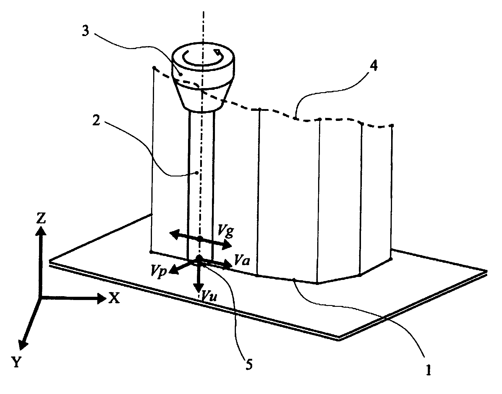
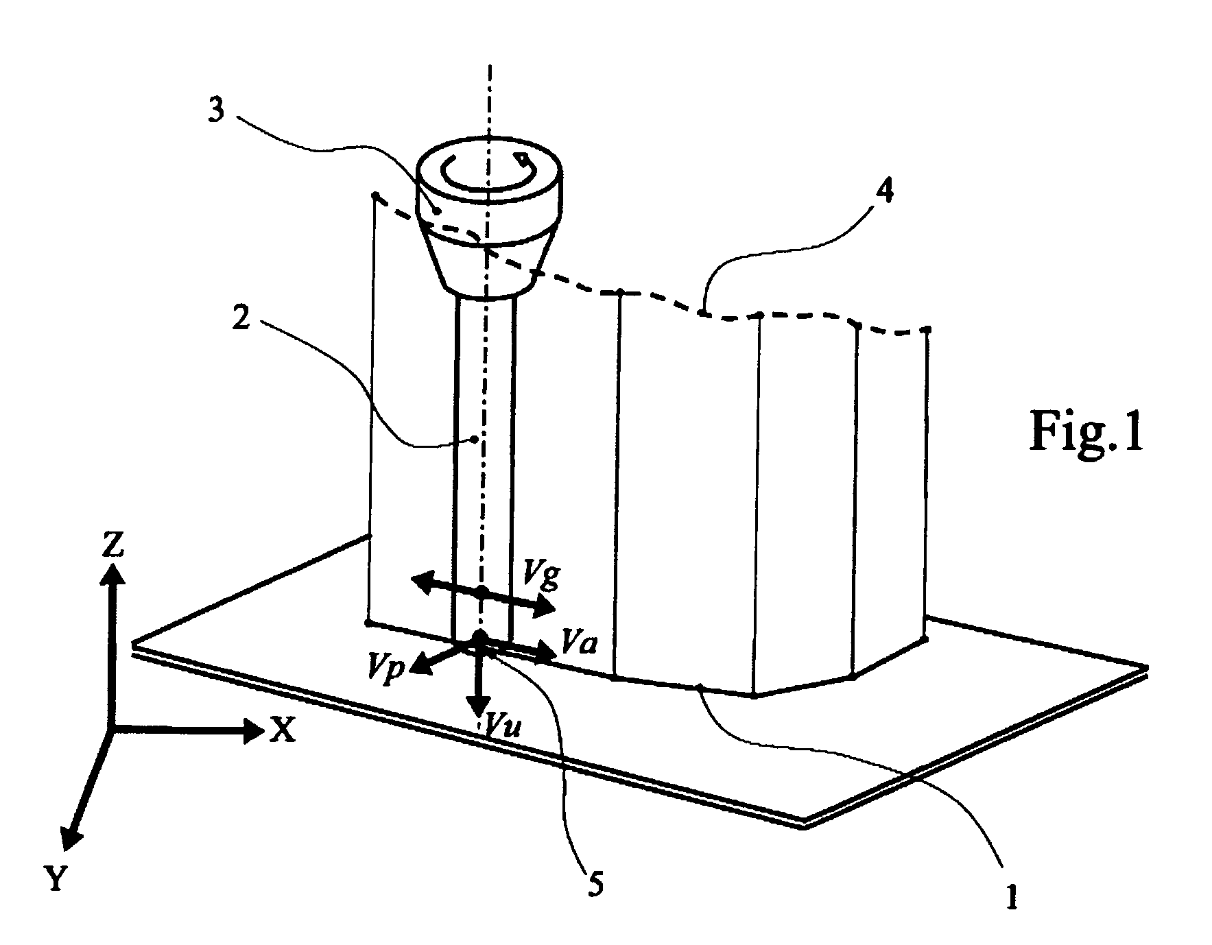
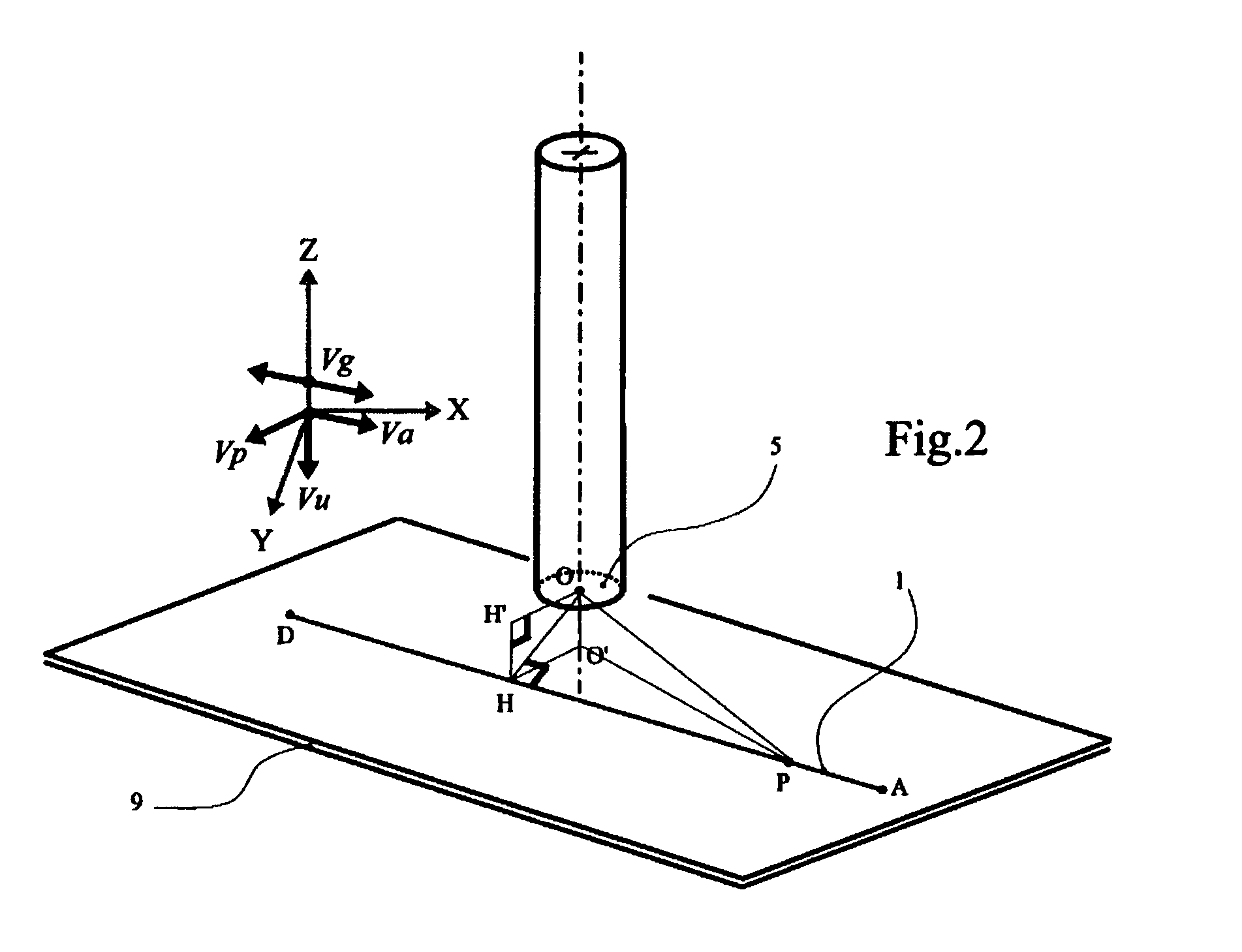
[0047]In order to explain the invention in a detailed manner, a number of execution modes will be explained hereinbelow. However, first, it is necessary to define the following specific concepts: Nominal Trajectory, Control Vectors, Advance Vector, Gap Vector, Wear Vector, Position Error, Position Vector, Inter-Segment Bisecting Line.

[0048]Referring to FIG. 1, the Nominal Trajectory is defined by means of a computer file supplied upstream of the machine's numerical control system; this is a succession of linear segments 1 or blocks defined relative to a part coordinate system X,Y,Z. The Nominal Trajectory describes, at each layer, the movement of the tool 2 as it ought to proceed if no disturbance were to occur during machining and if there were no tool wear. However, since there is usually wear, the tool holder 3, in order to compensate for this wear, must follow in real time a trajectory 4 which constantly drifts relative to the Nominal Trajectory 1, while the end of the tool 5, d...


PUM

PropertyMeasurementUnit
Angleaaaaaaaaaa
Speedaaaaaaaaaa
Symmetryaaaaaaaaaa

Abstract

Spark-erosion machining method and machine implementing a machining gap, a process regulator, a numerical control system, a Nominal Trajectory. The latter describes the movement of the tool electrode relative to the part as it ought to proceed if no disturbance were to occur during the machining. Information contained in the Nominal Trajectory is used to define at least two control vectors Vg, Vp which orient, within the coordinate system XYZ, two independent regulation movements. The first, or Gap Vector Vg, defines the direction in which a first regulation movement of the axes of the machine must be performed to maintain the removal of material. The second, or Position Vector Vp, defines the direction in which a second regulation movement of the axes of the machining machine must be performed to correct a tool electrode position error. The respective amplitudes of the regulation movements are calculated in real time by the process regulator.

Description

BACKGROUND OF THE INVENTION[0001]The invention relates to a spark-erosion machining method and to a machine implementing:[0002]a machining gap, situated between a tool electrode and a part, both conductors of electricity, a gap within which a multitude of erosive electrical discharges are generated, constituting a machining edge which is displaced according to the movements of the tool electrode,[0003]a dielectric medium present within the machining gap,[0004]said tool electrode being of cylindrical or tubular shape, moved along a number of axes of the machining machine relative to the machining edge and the part, x[0005]a process regulator,[0006]a numerical control system for controlling the displacements of the various axes of the machining machine,[0007]a Nominal Trajectory of the tool electrode defined by means of a computer file supplied upstream of the numerical control system of the machining machine and consisting of a succession of linear segments defined relative to a part...

Claims


Application Information

Patent Timeline
IPC IPC(8): B23H1/04
CPCB23H7/18B23H7/20B23H7/26G05B19/19B23H7/30B23H2400/10G05B2219/50331B23H7/28
Inventor TRICARICO, CLAUDIOROLLET, CLAUDEJAQUES, FABRICEDIOT, JEAN-CLAUDE
Owner AGIE CHARMILLES
Why Eureka
Try Eureka