
Method for Operating a Heating Element in a Motor Vehicle by Pulse Width Modulation

a technology of pulse width and heating element, which is applied in the direction of heating element shapes, ohmic-resistance heating details, incandescent ignition for engines, etc., can solve the problems of premature failure of glow plugs and worse ignition behavior, so as to prevent a rise in supply voltage, the effect of reducing the influence of vehicle electrical system voltage on the temperature of the heating elemen

Inactive Publication Date: 2011-03-17
BORGWARNER BERU SYST
View PDF3 Cites 2 Cited by
  • Summary
  • Abstract
  • Description
  • Claims
  • Application Information

AI Technical Summary

Benefits of technology

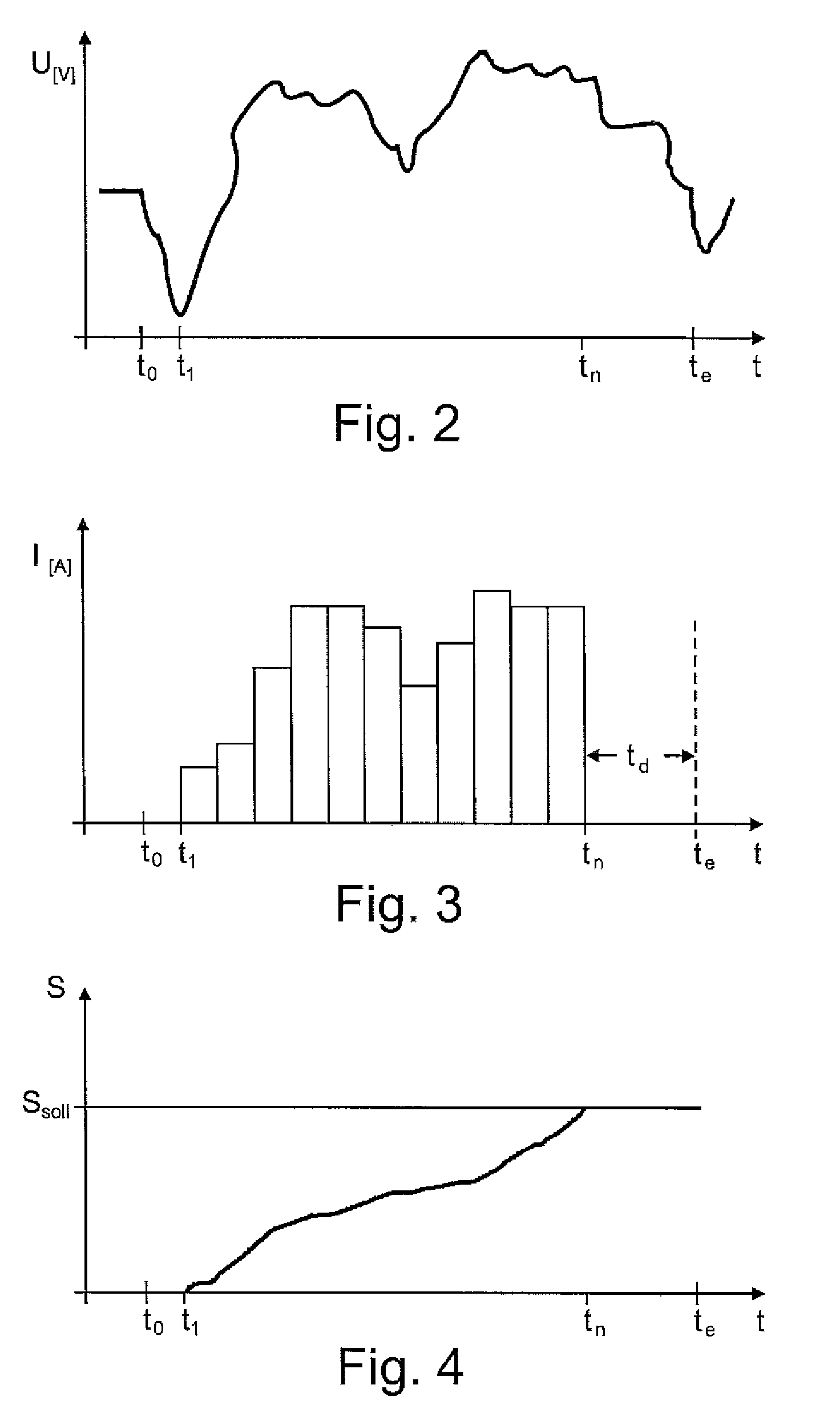
[0005]A method according to the invention prevents a rise in the supply voltage during a voltage pulse from resulting in overheating of the heating element. According to the invention, the energy that is fed during a voltage pulse is approximately determined and monitored, so that a voltage pulse can be shortened if a rise in the supply voltage occurs. The impact of fluctuations of the vehicle electrical system voltage on the temperature of the heating element can advantageously be reduced in this way. Advantageously, a method according to the invention can thus increase the service life of a glow plug, without impairing the ignition behavior of a diesel engine.
[0009]In a method according to the invention, a voltage pulse is preferably not ended until the sum value has reached the target value. In this way, it is possible to precisely end a voltage pulse when the energy that is fed into the heating element approximately corresponds to a target value.

Problems solved by technology

By feeding the energy that is required to maintain a desired operating temperature into a glow plug by way of pulse width modulation on a time average, a drop in the temperature, which would result in worse ignition behavior, and also overheating, which would result in premature failure of the glow plug, can be counteracted.

Method used


Image

  • Method for Operating a Heating Element in a Motor Vehicle by Pulse Width Modulation
  • Method for Operating a Heating Element in a Motor Vehicle by Pulse Width Modulation
  • Method for Operating a Heating Element in a Motor Vehicle by Pulse Width Modulation

Examples


Embodiment Construction

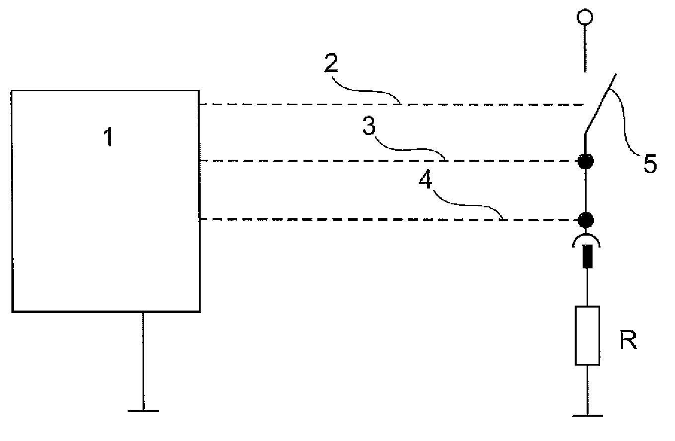
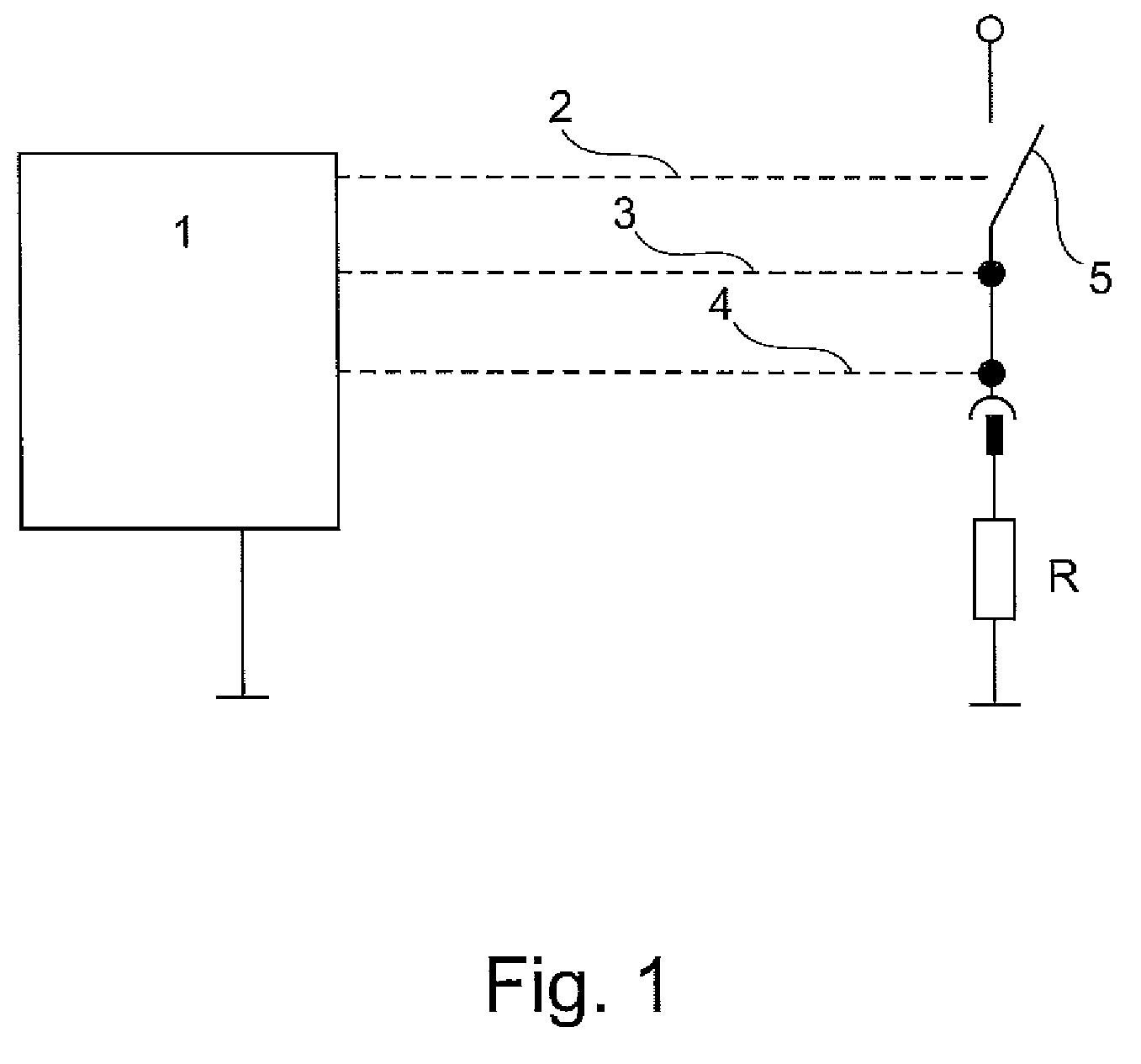
[0019]FIG. 1 is a schematic illustration of the heating resistor R of a glow plug, which is connected to the vehicle electrical system of a motor vehicle by way of a switch 5. The switch 5 is actuated by a glow plug controller 1, which can be configured as a microcontroller or microprocessor, for example. The switch 5 is a semiconductor power switch, preferably a field effect transistor, such as a MOSFET. The switch 5 is connected to the glow plug controller 1 by way of a control line 2. The glow plug controller 1 measures the current flowing through the heating element R. A corresponding current signal is made available to the glow plug controller 1 by way of the signal line 3. The glow plug controller 1 also measures the voltage that is present at the heating element R. A corresponding voltage signal is made available to the glow plug controller 1 by way of the signal line 4. Both the heating element R of the glow plug and the glow plug controller 1 are connected to ground by appr...


PUM

PropertyMeasurementUnit
Currentaaaaaaaaaa
Electric potential / voltageaaaaaaaaaa
Energyaaaaaaaaaa

Abstract

The invention relates to a method for operating a heating element in a motor vehicle by pulse width modulation, wherein fluctuations in the supply voltage are compensated for by adapting the duty cycle so as to achieve a desired heating output. According to the invention, during a voltage pulse the voltage that is present at the heating element and / or the current flowing through the heating element are measured at specified intervals, and the measured values or values determined therefrom are added to calculate a sum value, which rises with the energy that is fed into the heating element by the voltage pulse, and the voltage pulse is ended at the latest when the sum value has reached a target value. The invention furthermore relates to a glow plug controller for carrying out the method according to the invention.

Description

[0001]The invention relates to a method for operating a heating element in a motor vehicle by pulse width modulation, wherein fluctuations in the supply voltage are compensated for by adapting the duty cycle so as to achieve a desired heating output.[0002]Such a method is described in DE 10 2006 010 081 A1. In the known method, the energy to be fed into a glow plug during a period with a voltage pulse is established as a function of a desired target temperature of the glow plug, and a corresponding pulse duration is specified while taking the current supply voltage for the current period into consideration. By measuring the current and voltage, the actual heating energy that is introduced during the voltage pulse is then determined, and an energy deficit or an energy surplus is compensated for during one of the subsequent periods.[0003]The known method can be used to regulate the temperature of a glow plug to an operating temperature which enables optimal ignition behavior. By feedi...

Claims


Application Information

Patent Timeline
IPC IPC(8): B60L1/02H05B3/02
CPCF02D2041/2027F02D2041/2051F02P19/022F02D2200/503F02D2041/2058
Inventor BLANC, MARTINBLEIL, ANDREAS
Owner BORGWARNER BERU SYST
Learn More