Wireless communication apparatus for changing directional pattern of variable directivity antenna according to variations in radio wave propagation enviroment

a technology of variable directivity and wireless communication, applied in the direction of transmission, transmission monitoring, modulation, etc., can solve the problem that the wireless communication apparatus sometimes fails to correctly transmit data, and achieve the effect of higher speed

Inactive Publication Date: 2011-03-17
PANASONIC CORP
View PDF18 Cites 18 Cited by
  • Summary
  • Abstract
  • Description
  • Claims
  • Application Information

AI Technical Summary

Benefits of technology

[0023]The wireless communication apparatus according to the present invention has the storage device and the controller. The storage device previously stores composite directional pattern classification information on classification of the plurality of composite directional patterns into a plurality of composite directional pattern groups set by using a first parameter representing a quality level of a wireless signal received by the variable directivity antenna apparatus. The controller selects one composite directional pattern from among the plurality of composite directional patterns based on the first parameter and a second parameter, and controls the composite directional pattern of the variable directivity antenna apparatus so that the variable directivity antenna apparatus forms a selected composite directional pattern, where the second parameter represents the quality level of the wireless signal and is different from the first parameter. Therefore, even when the radio wave propagation environment changes, the data signal can be transmitted and received at higher speed and more stably than in the prior art.

Problems solved by technology

The wireless communication apparatus has the above-described advantages, however, when installed in a space where a number of reflective objects are placed, the wireless communication apparatus sometimes fails to correctly transmit data because of deteriorations in transmission performance due to the influence of fading caused by delayed waves incoming after reflected by the objects, since the wireless communication apparatus perform communications by emitting electromagnetic waves in the space.

Method used


Image

  • Wireless communication apparatus for changing directional pattern of variable directivity antenna according to variations in radio wave propagation enviroment
  • Wireless communication apparatus for changing directional pattern of variable directivity antenna according to variations in radio wave propagation enviroment
  • Wireless communication apparatus for changing directional pattern of variable directivity antenna according to variations in radio wave propagation enviroment

Examples


first preferred embodiment

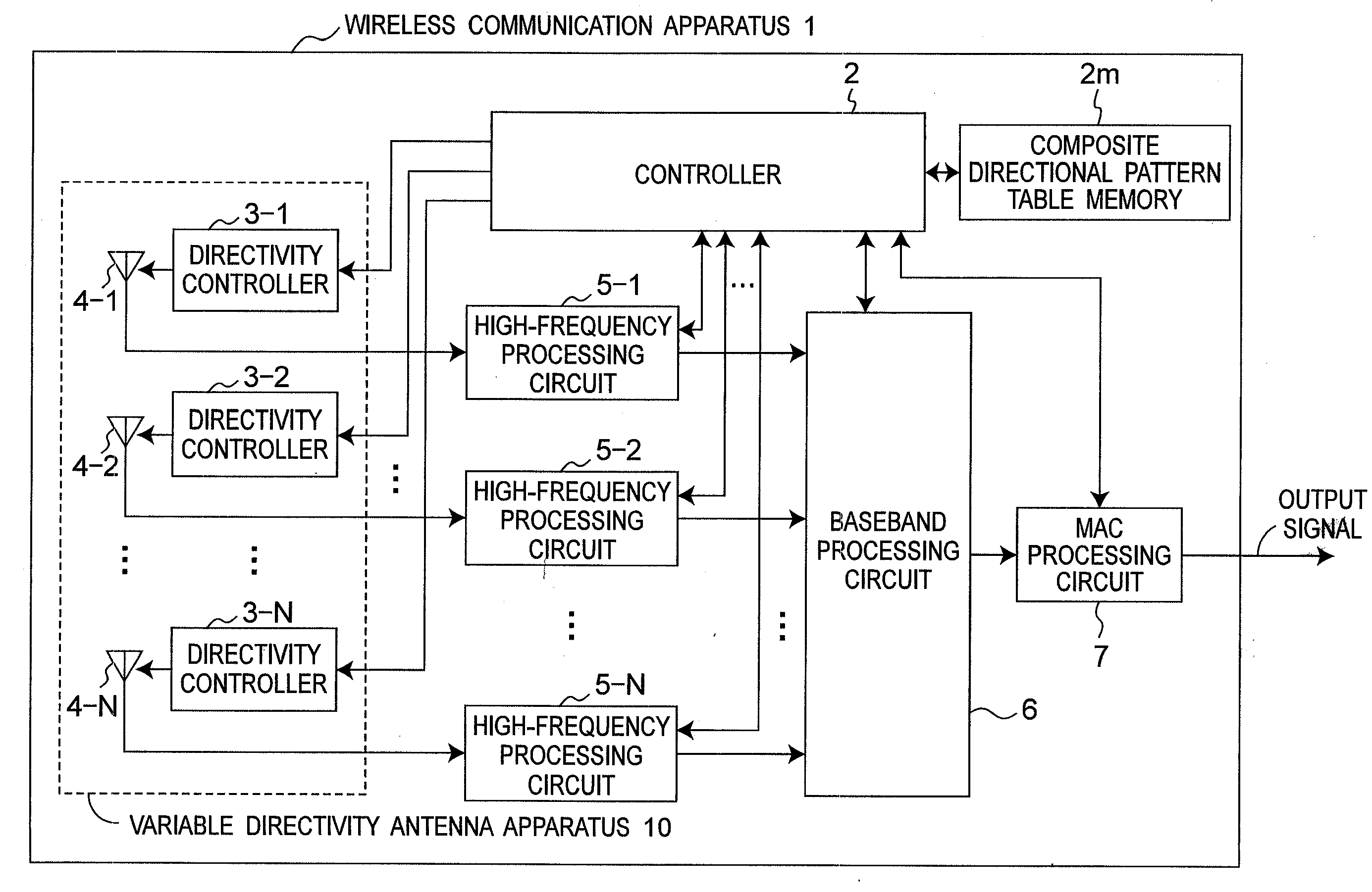
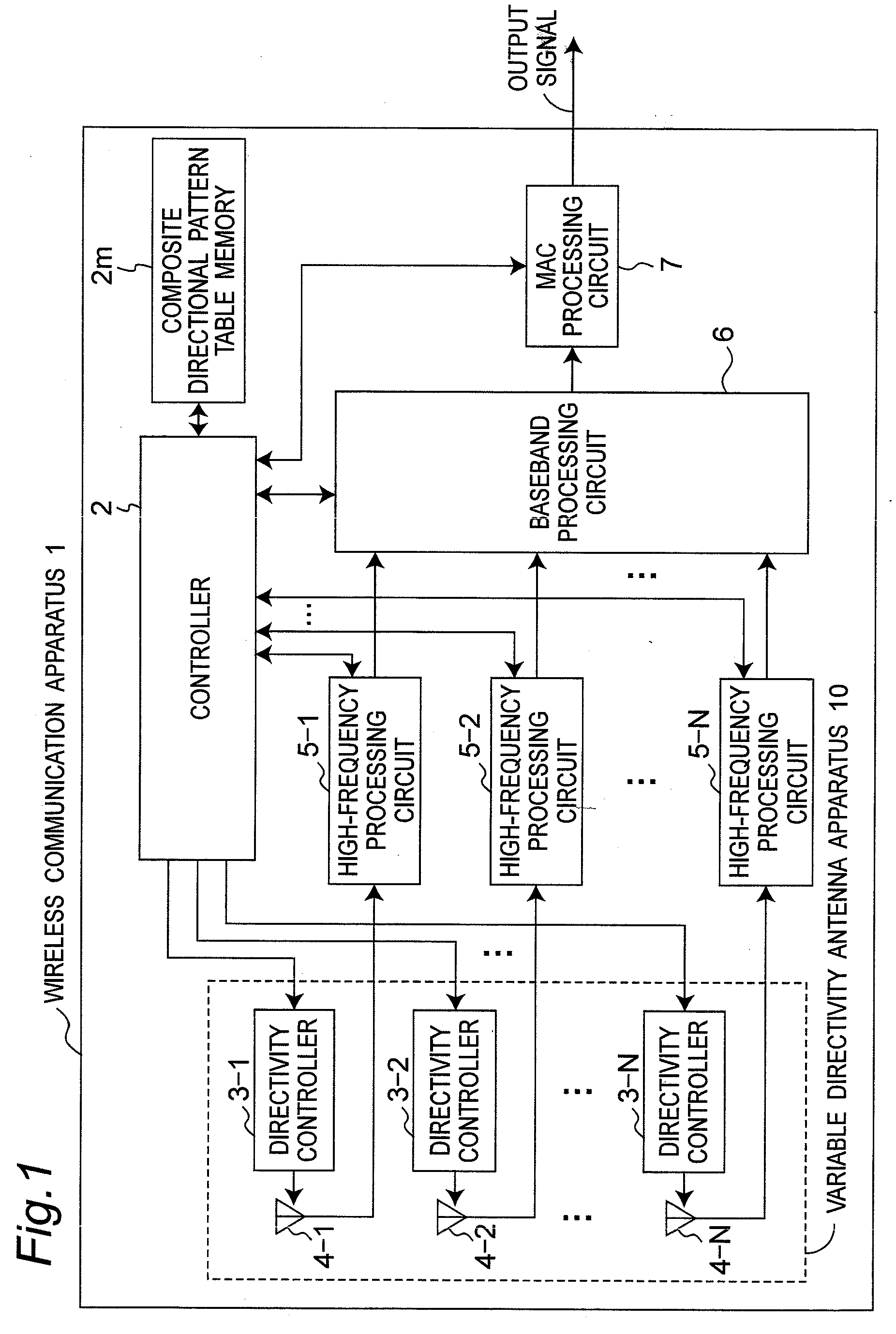
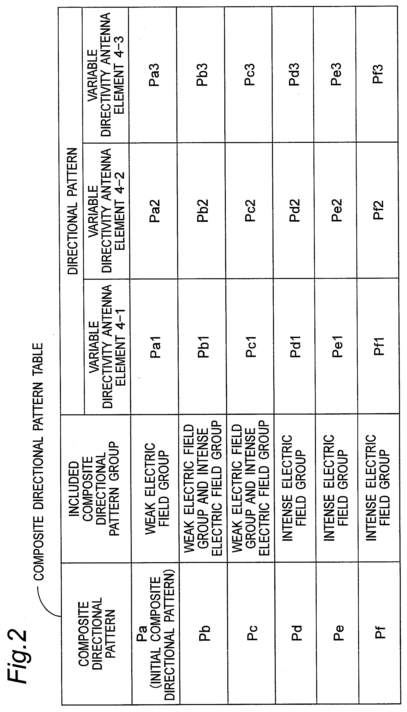
[0040]FIG. 1 is a block diagram showing a configuration of a wireless communication apparatus 1 according to the first preferred embodiment of the present invention. In the present preferred embodiment, a composite directional pattern table memory 2m stores therein composite directional pattern classification information of a variable directivity antenna apparatus 10 in a form of a table including the composite directional pattern classification information. FIG. 2 is a chart showing one example of a composite directional pattern table stored in the composite directional pattern table memory 2m of FIG. 1. In addition, FIG. 3 is a chart showing one example of composite directional patterns Pa to Pf of the composite directional pattern table of FIG. 2. Further, FIG. 4 is a flow chart showing a directional pattern control process executed by a controller 2 of FIG. 1, and FIG. 5 to FIG. 7 are flow charts showing a composite directional pattern group selecting process S2 of FIG. 4, a com...

second modified preferred embodiment

of First Preferred Embodiment

[0077]FIG. 9 is a flow chart showing a composite directional pattern selecting process S4B according to the second modified preferred embodiment of the first preferred embodiment of the present invention. As compared with the first preferred embodiment, the process of the second modified preferred embodiment is obtained by replacing the composite directional pattern selecting process S4 (FIG. 6) executed by the controller 2 of FIG. 1 with the composite directional pattern selecting process S4B.

[0078]Referring to FIG. 9, first of all, the processes of steps S31 to S40 are performed in a manner similar to that of the composite directional pattern selecting process S4 of FIG. 6. Then, subsequent to step S40, a composite directional pattern candidate having the smallest average value of the PER is selected at step S49, one is substituted into the flag IF representing whether or not the composite directional pattern has been able to be selected at step S44, a...

third modified preferred embodiment

of First Preferred Embodiment

[0080]FIG. 10 is a flow chart showing a composite directional pattern selecting process S4C according to the third modified preferred embodiment of the first preferred embodiment of the present invention. As compared with the second modified embodiment, the process of the third modified preferred embodiment is obtained by replacing the composite directional pattern selecting process S4B (FIG. 9) executed by the controller 2 of FIG. 1 with the composite directional pattern selecting process S4C.

[0081]Referring to FIG. 10, first of all, a first candidate is selected from among the composite directional pattern candidates at step S32 in a manner similar to that of the composite directional pattern selecting process S4A (FIG. 8) of the first modified preferred embodiment, and the respective directional patterns of the variable directivity antenna elements 4-1 to 4-N are controlled so that the variable directivity antenna apparatus 10 forms the selected compo...


PUM


Abstract

When a variable directivity antenna apparatus is controlled to form an initial composite directional pattern, RSSI is measured, and a weak electric field group or an intense electric field group is selected based on the measured RSSI. When the variable directivity antenna apparatus is controlled to form the composite directional patterns included in the selected composite directional pattern group, PER for each of the composite directional patterns is measured, and one composite directional pattern is selected from among the composite directional patterns included in the selected composite directional pattern group based on the measured PER, so that the variable directivity antenna apparatus is controlled to form the selected composite directional pattern.

Description

TECHNICAL FIELD[0001]The present invention relates to a wireless communication apparatus. In particular, the present invention relates to a wireless communication apparatus which changes a directional pattern of a variable directivity antenna thereof according to variations in a radio wave propagation environment.BACKGROUND ART[0002]Among network configurations in which information terminals are connected to each other, a network that uses wireless communication has such advantages as superiority in portability of the information terminals, freedom in the arrangement of the information terminals, and reduction of the weight of the information terminals by removing cables for connections between the information terminals, as compared with a network that uses wire communication. For the above reasons, wireless communication apparatuses have been not only utilized for data transmissions between personal computers but also built in many home electric appliances and utilized for audio an...

Claims


Application Information

Patent Timeline
Patent Type & Authority Applications(United States)
IPC IPC(8): H04B15/00H04B1/00
CPCH04B17/318H04B7/0615
Inventor SHIOTSUKI, AKIHIKOSHINKAI, SOTARONAGOSHI, MASAHIKOYURUGI, HIROYUKINOGUCHI, WATARUTANAKA, KOICHIRO
Owner PANASONIC CORP
Why Eureka
Try Eureka