Method, System, Computer Program Product, and Data Processing Program for Verification of Logic Circuit Designs Using Dynamic Clock Gating

a logic circuit and clock gating technology, applied in cad circuit design, program control, instruments, etc., can solve the problems of serious performance degradation, art functional verification methods cannot verify the design goal, and dynamic clock gating adds additional complexity to logic circuit design

Inactive Publication Date: 2011-03-17
GLOBALFOUNDRIES INC
View PDF9 Cites 13 Cited by
  • Summary
  • Abstract
  • Description
  • Claims
  • Application Information

AI Technical Summary

Benefits of technology

[0029]All in all, embodiments of the present invention disclosed herein are able to verify the design goal for logic circuit designs using dynamic clock gating to behave completely independent on the dynamic clock gating configuration. So embodiments of the present invention do guarantee functional correctness of the logic circuit design and are able to detect any changes in the behavior of the logic circuit design based on the dynamic clock gating configuration that could result in serious performance degradations.

Problems solved by technology

However, dynamic clock gating adds additional complexity to the logic circuit design which has to behave completely independent on the dynamic clock gating configuration.
This approach relies on interface signals and / or data only and, for example, does not check performance behavior of the logic circuit design that is not described by the interface specification.
The described state of the art functional verification methods can not verify the design goal for logic circuit designs using dynamic clock gating to behave completely independent on the dynamic clock gating configuration.
The state of the art verification methods only guarantee functional correctness of the logic circuit design and are not able to detect any changes in the behavior of the logic circuit design based on the dynamic clock gating configuration that could result in serious performance degradations.
Due to a clock gating problem the behavior of the LRU-Algorithm can be changed in a problematic way.
For example, in our case the behavior changed in a way that the cache behaved as a two way associative cache only, resulting in a significant reduction in system performance.
Another example of problems which could arise in a logic circuit design due to dynamic clock gating is an arbiter.
Any difference in the results of the at least two simulation runs for the different clock gating configurations is considered to be an error.
Obviously, no exhaustive testing is possible in a reasonable amount of time.

Method used


Image

  • Method, System, Computer Program Product, and Data Processing Program for Verification of Logic Circuit Designs Using Dynamic Clock Gating
  • Method, System, Computer Program Product, and Data Processing Program for Verification of Logic Circuit Designs Using Dynamic Clock Gating
  • Method, System, Computer Program Product, and Data Processing Program for Verification of Logic Circuit Designs Using Dynamic Clock Gating

Examples


Embodiment Construction

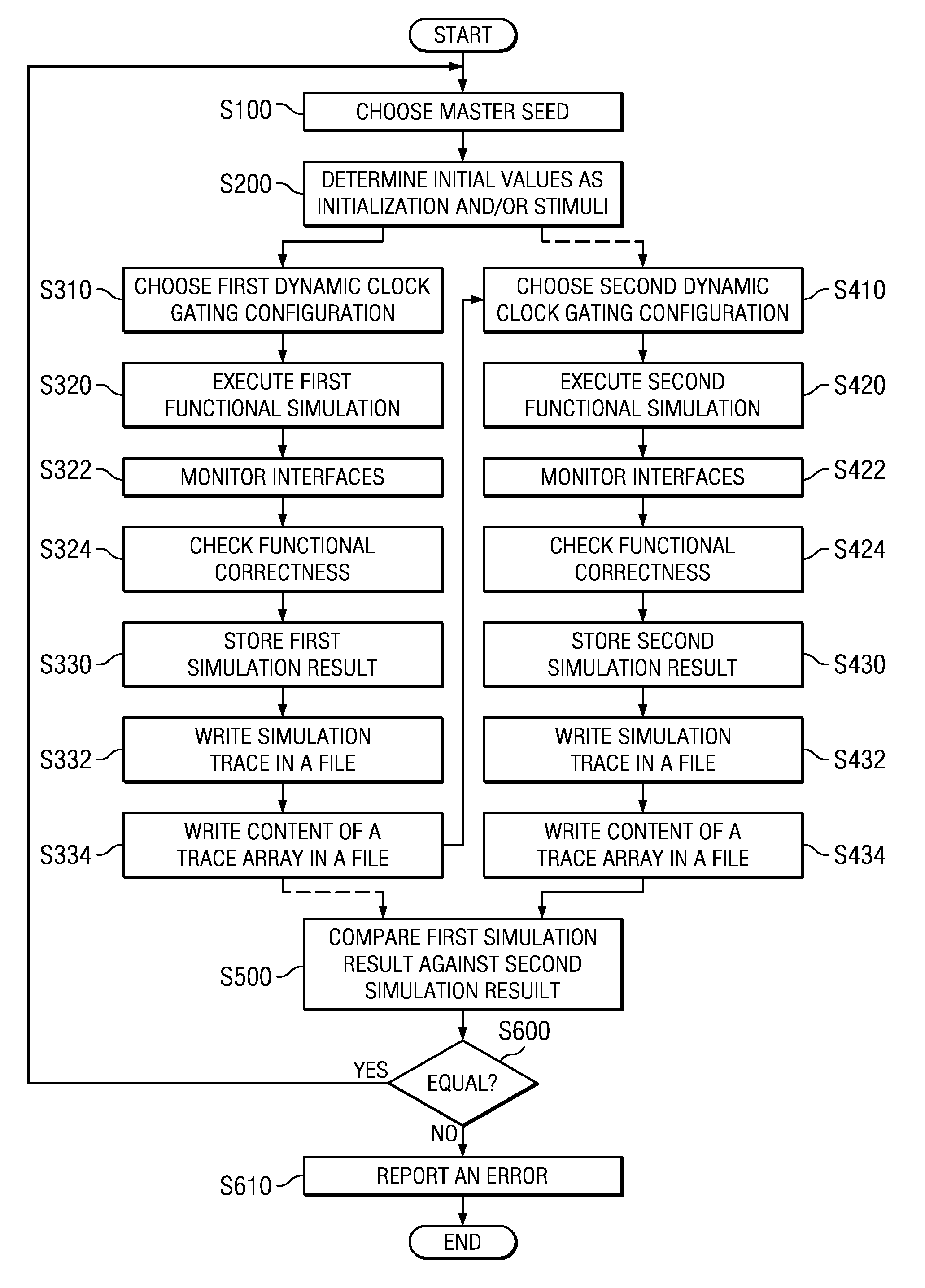
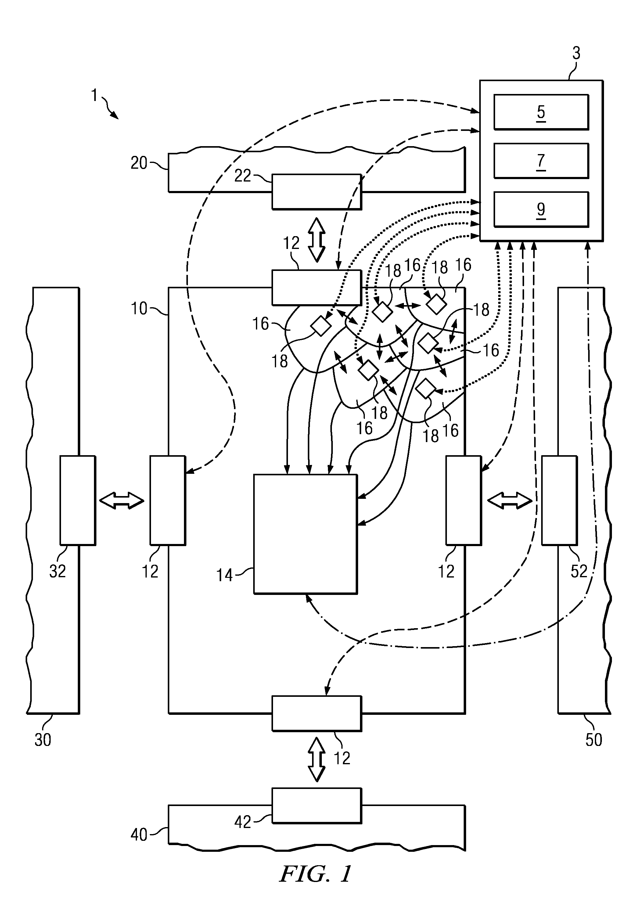
[0037]Referring to FIG. 1, the shown embodiment of the invention employs a system 1 for verifying a logic circuit design using dynamic clock gating, wherein the logic circuit design comprise processors, cores, units, macros and / or sub macros for example.

[0038]Referring to FIG. 1, the shown embodiment of the invention employs a system 1 for verifying a logic circuit design comprising a multiple of logic circuits 10, 20, 30, 40, 50 and a verification environment 3, whereas just the logic circuit 10 is shown in more detail for the purpose of clearness and a better understanding of the present invention. In the following detailed description, the invention is especially explained with regard to the logic circuit 10. According to the invention, the verification environment 3 chooses at least one master seed to determine initial values as initialization for the logic circuits 10, 20, 30, 40, 50 and / or stimuli data for at least one interface 12, 22, 32, 43, 52 of the logic circuits 10, 20,...


PUM


Abstract

A method and system for verifying a logic circuit design using dynamic clock gating is disclosed. The method comprises choosing at least one master seed to determine initial values as initialization for said logic circuit and/or stimuli data for at least one interface of said logic circuit, choosing at least two different dynamic clock gating configurations for every chosen master seed, executing a functional simulation with said logic circuit for every chosen dynamic clock gating configuration by using said determined initialization and/or stimuli data based on a corresponding master seed, comparing simulation results of functional simulations against each other executed with said logic circuit for at least two different chosen dynamic clock gating configurations, and reporting an error if said at least two simulation results are not identical.

Description

BACKGROUND[0001]1. Field[0002]The present invention relates in general to the field of verifying logic circuit designs, which are especially used in processor systems, and in particular to a method and a system for verification of logic circuit designs using dynamic clock gating, wherein the logic circuit design comprise processors, cores, units, macros and / or sub macros for example. Still more particularly, the present invention relates to a data processing program and a computer program product for verification of logic circuit designs using dynamic clock gating.[0003]2. Description of the Related Art[0004]Dynamic clock gating is one method for minimizing the power consumption of logic circuitries which are used in electronic devices. The main idea is to disable clocking of logic components that are currently not in use. Clocking is enabled again based on incoming stimuli data and / or signals to that logic component. Dynamic clock gating is a fine grained mechanism to enable and di...

Claims


Application Information

Patent Timeline
Patent Type & Authority Applications(United States)
IPC IPC(8): G06F17/50
CPCG06F2217/78G06F17/5022G06F30/33G06F2119/06
Inventor HABERMANN, CHRISTIANJACOBI, CHRISTIANPFLANZ, MATTHIASTAST, HANS-WERNERWINKELMANN, RALF
Owner GLOBALFOUNDRIES INC
Why Eureka
Try Eureka