Separator device

Inactive Publication Date: 2011-03-24
ROLLS ROYCE PLC
View PDF20 Cites 39 Cited by
  • Summary
  • Abstract
  • Description
  • Claims
  • Application Information

AI Technical Summary

Benefits of technology

[0021]The through-holes may be formed as slots extending substantially in the radial direction of the engine. This arrangement can allow a sufficient flow of cooling air to pass through the slots to form the second portion of the cooling air. Slots may also be less susceptible to blockage than e.g. circular holes.
[0022]The slots may narrow in width with increasing radial distance. As the larg

Problems solved by technology

The cooling air bled from the compressor that is used to cool the hot turbine components is not used fully to extract work from the turbine.
Therefore, as extracting coolant flow has an adverse effect on the engine operating efficiency, it is important to minimise the use of cooling air and maximise its effectiveness.
These small holes are susceptible to blockage from the inside, by air-borne dirt particles or from compressor rub-seal material.
In addition the holes can become blocked from the outside, by dirt particles and combustion products, that attach themselves to the gas washed surfaces of the NGV, particularly the leading edge and pressure surfaces.
Engines on aircraft that operate out of or over sandy areas such as desert are particularly susceptible to sand ingestion and cooling hole blockage.
Partially blocked film cooling holes substantially reduce the quantity of cooling air passed by the cooling system, which causes the NGV to overheat, loss of the NGV thermal barrier coating (TBC), and ultimately premature low cycle fatigue cracking and oxidation of the gas washed surfaces of the NGV.
Eventually the NGVs will burn away, particularly at the leading and trail

Method used


Image

  • Separator device
  • Separator device
  • Separator device

Examples


Embodiment Construction

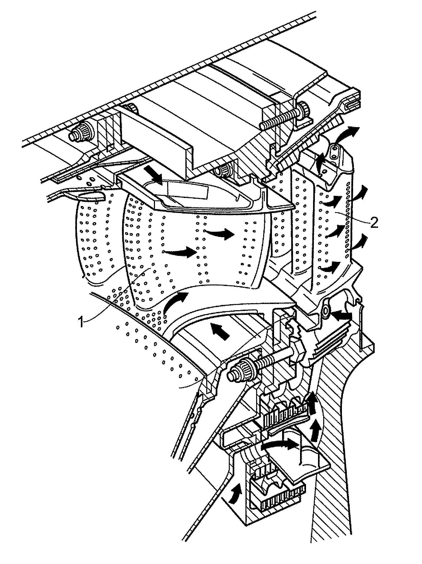
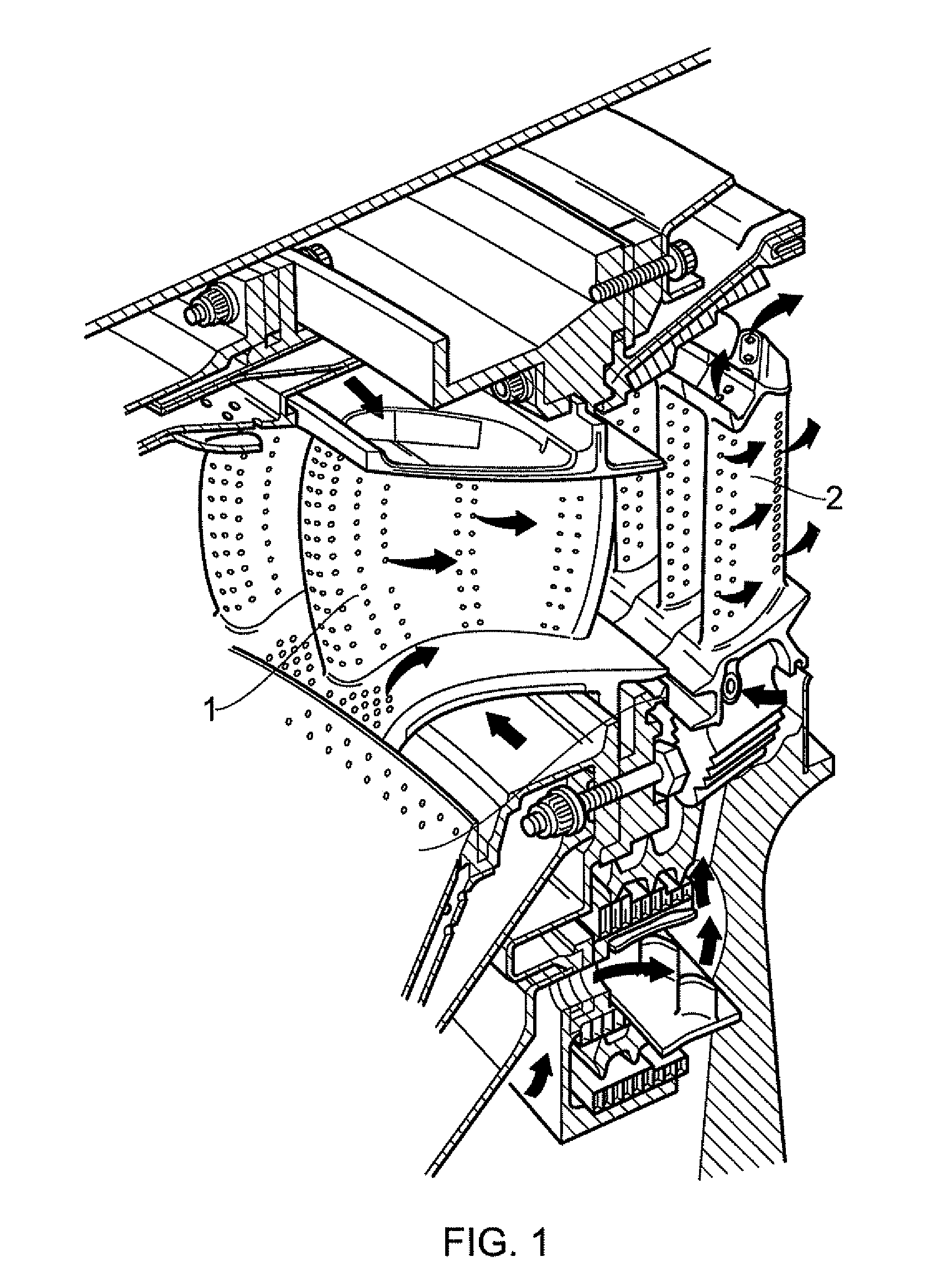
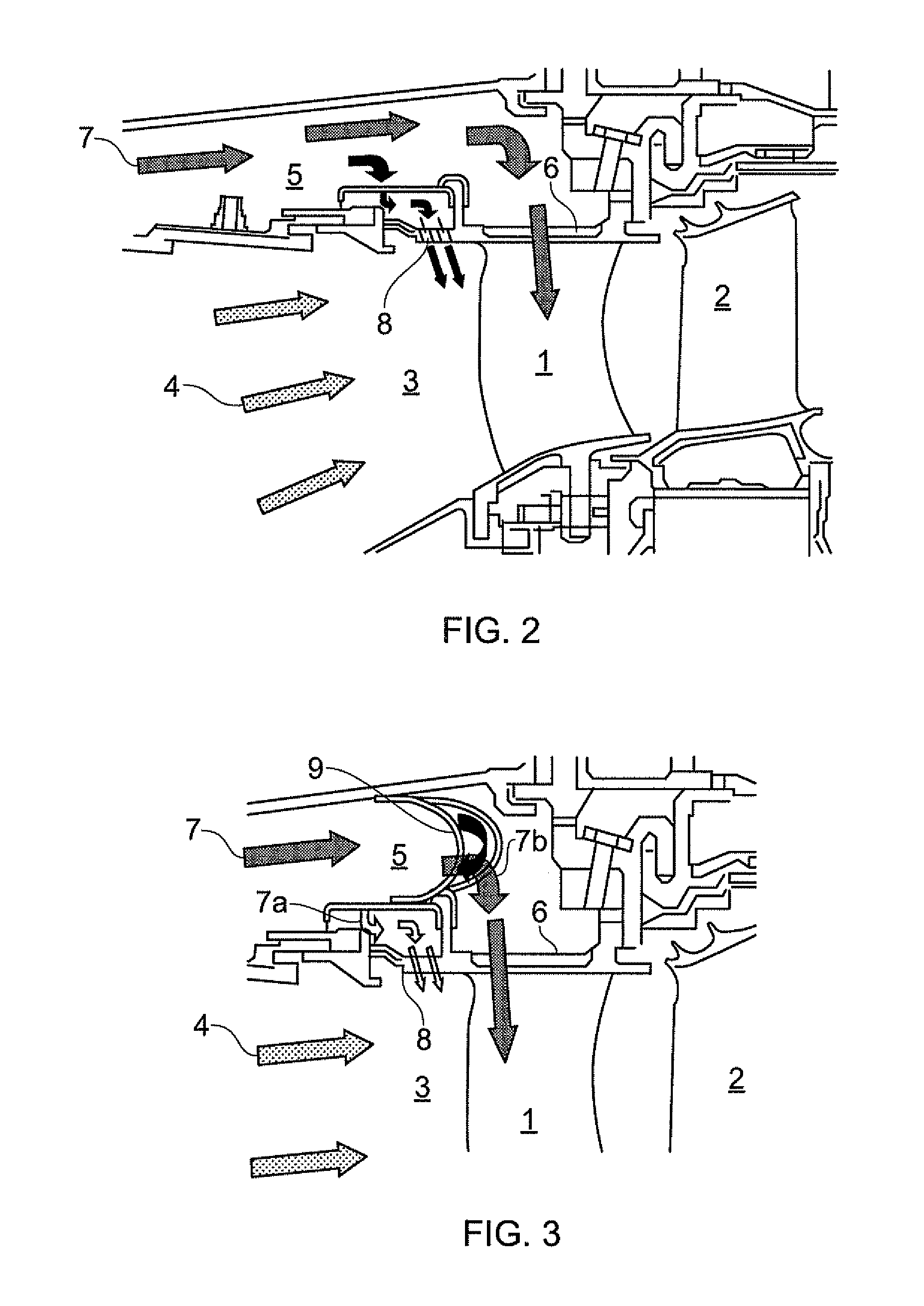
[0038]FIG. 2 shows a longitudinal cross-sectional view through an HP turbine of a gas turbine engine. An NGV 1 and a turbine blade 2 extend across the working gas annulus 3. Arrows 4 indicate the general flow direction of the working gas. A radially outer annular conduit 5 bypasses the combustor to carry pressurised cooling air from the compressor to a radially outer feed opening 6 into the interior of the NGV. The general flow direction of the cooling air is indicated by arrows 7. Some of the cooling air, instead of reaching the opening, passes through radially outer discharge nozzles 8 which feed cooling air into the working gas annulus upstream of the NGV to dilute the hot working gas adjacent to the gas path end-walls. Dirty contaminated air mainly passes into the NGV rather than through the discharge nozzles and can lead to internal blockage of film cooling holes which extend from the interior to the exterior of the NGV.

[0039]FIG. 3 shows a longitudinal cross-sectional view thr...


PUM

PropertyMeasurementUnit
Flow rateaaaaaaaaaa
Concentrationaaaaaaaaaa
Heightaaaaaaaaaa

Abstract

A separator device is provided for separating dirt particles from a flow of cooling air fed to airfoils of the turbine section of a gas turbine engine. In use the separator device extends across a conduit which bypasses the combustor of the engine to convey pressurised cooling air carrying dirt particles from the compressor section of the engine to openings which direct the air into the airfoils. The separator device is configured to direct a first portion of the impinging cooling air flow away from the openings and to allow a second portion of the impinging cooling air to continue to the openings. The first portion of cooling air has a higher concentration of the coarsest dirt particles carried by the cooling air than the second portion of cooling air.

Description

FIELD OF THE INVENTION[0001]The present invention relates to a separator device for separating dirt particles from a flow of cooling air fed to airfoils of the turbine section of a gas turbine engine.BACKGROUND OF THE INVENTION[0002]The performance of gas turbine engines, whether measured in terms of efficiency or specific output, is improved by increasing the turbine gas temperature. In modern engines, the high pressure (HP) working gas temperatures are hotter than the melting point of the material of the blades and vanes, necessitating internal air cooling of these airfoil components. During its passage through the engine, the mean temperature of the gas stream decreases as power is extracted. Nonetheless, in some engines, the intermediate pressure (IP) and low pressure (LP) turbines are also internally cooled.[0003]FIG. 1 shows an isometric view of a typical HP stage of a cooled turbine. Cooling air flows are indicated by arrows.[0004]HP turbine nozzle guide vanes 1 (NGVs) consum...

Claims


Application Information

Patent Timeline
IPC IPC(8): F02G3/00B01D50/00
CPCF01D25/32F02C7/18F05D2260/607Y02T50/67Y02T50/671Y02T50/675Y02T50/676F05D2240/81F05D2250/184F05D2260/202F05D2250/181B01D45/04B01D46/0039F01D9/065Y02T50/60
Inventor TIBBOTT, IANJACKSON, DOUGAL
Owner ROLLS ROYCE PLC
Why Eureka
Try Eureka