
Narrowband de-icing and ice release system and method

a narrowband and ice release technology, applied in the direction of cleaning with liquids, furniture, lighting and heating apparatus, etc., can solve the problems of inefficient transfer of heat from the inside surface of the windshield to the windshield glass or other material, the de-icing speed and efficiency of the automotive windshield is not optimized, and the de-icing speed is relatively slow and inefficien

Active Publication Date: 2011-03-24
PRESSCO IP LLC
View PDF26 Cites 21 Cited by
  • Summary
  • Abstract
  • Description
  • Claims
  • Application Information

AI Technical Summary

Benefits of technology

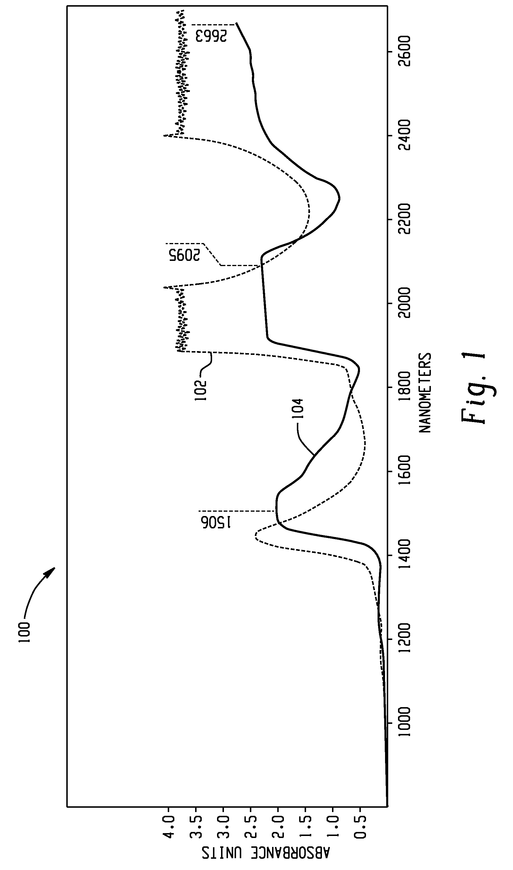
[0015]Another object of this invention is to provide a narrowband irradiation system and method which can melt ice by taking advantage of the absorption peaks of an element or compound from which ice may be formed or the ice itself.
[0016]Another object of the present invention is to provide an efficient de-icing or ice releasing system and method which can directly irradiate the interfacial ice on the substrate surface, thus turning it into water to provide easy release for the balance of the thickness of the ice.
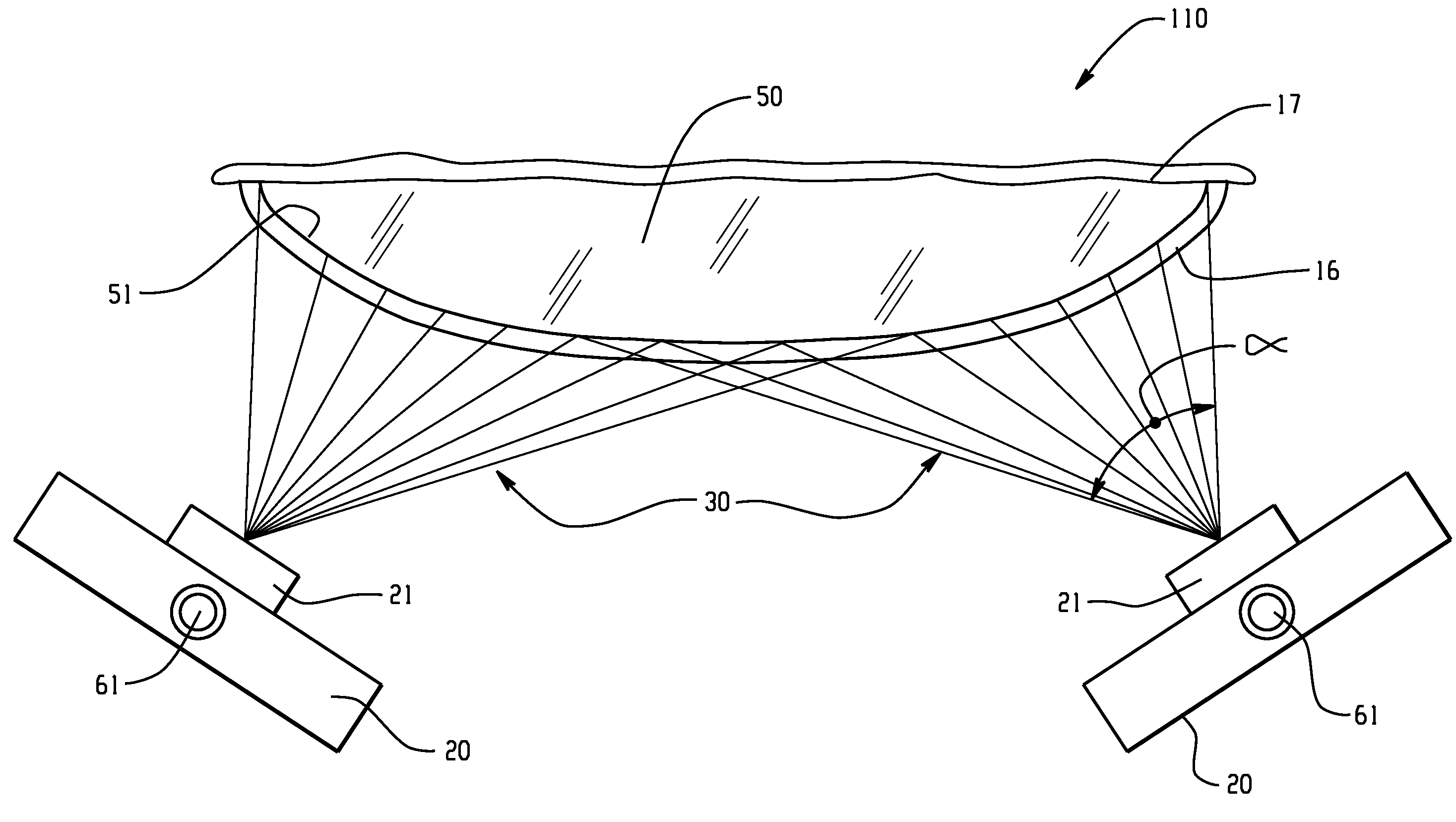
[0044]In another aspect of the presently described embodiments, the method comprises (a) providing a substrate item having an exterior surface on which ice has formed to be at least partially deiced, wherein a material comprising the said substrate is highly transmissive at an irradiation wavelength which will be employed and capable of total internal reflection, (b) close-coupling narrowband irradiation sources to at least one edge of the substrate material to provide a way of efficiently injecting narrowband irradiation at the irradiation wavelength into the substrate item, and, (c) activating the narrowband irradiation sources to create internal reflection of the irradiation such that the photons only escape the substrate item where the ice provides a path for escape by more closely matching the indexes of refraction of the substrate, thus irradiating the interfacial surface of the ice.

Problems solved by technology

Most traditional ice handling methods have common basic functionalities which have grown out of traditional methods and have not been efficiency optimized.
For example, automotive windshield de-icing is relatively slow and inefficient.
It relies upon convection from hot air, which is the result of a number of inefficient conversions starting with engine crank-case heat.
The convective air that is blown onto the inside surface of the windshield transfers its heat inefficiently to the windshield glass or other material.
As the windshield is heating up, it is also giving up large quantities of its heat energy to the atmosphere around the windshield, both in the interior and exterior of the vehicle.
In summary, the process of melting ice in order to clear the windshield for safe vision is a very slow, indirect, and inefficient process.
It also tends to be an uneven process because certain areas of the windshield warm faster than others.
The inherent unevenness of the convective heating process from the defroster blower has a tendency to allow various areas to refreeze, especially in inclement conditions where temperatures often fall below freezing.
Also, the traditional air blown convective defroster in an automobile can be annoyingly noisy.
During the warm up period, it also can cause a wind chill effect which is uncomfortable to the passengers.
It apparently has not been well accepted by consumers because of the wires which are annoying and distracting in the driver's field of view.
This technology, though, has many moving parts which dictate maintenance and potential failure modes.
The system also represents a substantial additional weight that the aircraft must carry aloft.
Perhaps more importantly, the viability of such a de-icing system in severe icing conditions has been recently questioned.
The chemical-based systems do not work well in many applications.
For example, in-flight wing de-icing is not practically accomplished with such systems.
Also, in some cases, chemical melting systems can cause ground water pollution issues and / or increase dependence on oil.
The system is extremely inefficient because it uses an external projection of long wave energy onto the wing and other surfaces of the plane which must completely melt 100% of the ice before the plane is ready to fly.
It has a massive disadvantage in that very powerful and heavy lasers and beam guiding equipment must be on-board the aircraft, thus creating a payload issue and a safety issue.
Further, and more importantly, a bad rain or snow storm would prevent the laser from scanning the critical surfaces by disturbing and scattering the laser beam before it can reach its targets.
This would render the de-icing system useless at a most needed time.
This is a major cause of inefficiency and it directly slows down the functionality of the de-icing or ice releasing systems.

Method used


Image

  • Narrowband de-icing and ice release system and method
  • Narrowband de-icing and ice release system and method
  • Narrowband de-icing and ice release system and method

Examples


Embodiment Construction

[0060]The present invention provides for a de-icing and ice release system and method incorporating Digital Heat Injection technology (DHI)—the fundamentals of which are detailed in a series of patents and / or patent applications including U.S. Pat. No. 7,425,296; U.S. application Ser. No. 11 / 351,030 (filed Feb. 9, 2006 as a continuation of U.S. Pat. No. 7,425,796); U.S. application Ser. No. 11 / 448,630 (filed Jun. 7, 2006); U.S. application Ser. No. 12 / 135,739 (filed Jun. 9, 2008); U.S. Provisional Application No. 61 / 224,822 (filed Jul. 10, 2009) (now corresponding to U.S. Ser. No. 12 / 834,742, filed Jul. 12, 2010); U.S. Provisional Application No. 61 / 224,765 (filed Jul. 10, 2009) (now corresponding to U.S. Ser. No. 12 / 718,919, filed Mar. 5, 2010); U.S. Provisional Application No. 61 / 231,944 (filed Aug. 6, 2009) (now corresponding to U.S. Ser. No. 12 / 852,311, filed Aug. 6, 2010) and, U.S. Provisional Application No. 61 / 157,799 (filed Mar. 5, 2009) (now corresponding to U.S. Ser. No. 1...


PUM


Abstract

A way of using narrowband irradiation to de-ice or release ice from a surface is provided. The methodology can be applied to a range of different types of de-icing from windshield de-icing to aircraft wing de-icing to releasing ice from the ice tray of an ice making machine. While there are many different specific applications, the concept and methodologies taught remain similar across all of them.

Description

[0001]This application is based on and claims priority to U.S. Provisional Application No. 61 / 243,669, filed Sep. 18, 2009, which is incorporated herein by reference in its entirety.BACKGROUND OF THE INVENTION[0002]This invention relates to a specific way of using narrowband irradiation to de-ice or release ice from a surface. The methodology can be applied to a range of different types of de-icing from windshield de-icing to aircraft wing de-icing to releasing ice from the ice tray of an ice making machine. While there are many different specific applications, the concept and methodologies taught remain similar across all of them.[0003]Historically, many different methodologies have been employed for addressing the problems of ice or the control of ice. The formation of ice can either be purposeful or problematic depending on the circumstances—but the desire to deal with ice in a controlled way is well documented in everyday living as well as the patent database. While it is beyond...

Claims


Application Information

Patent Timeline
IPC IPC(8): B08B7/00
CPCB64D15/00H01L33/00H01S5/00B08B7/0042
Inventor COCHRAN, DON W.KATZ, JONATHAN M.JOHNSON, BENJAMIN D.ROSS, III, DENWOOD F.
Owner PRESSCO IP LLC
Learn More