
Method and apparatus for cleaning a film seperating device

a separation device and film technology, applied in the direction of cleaning process and apparatus, cleaning using liquids, ultrafiltration, etc., can solve the problems of high depreciation expense, one-time investment and operating costs of membrane-based water treatment technology, and the price of membrane separation device has dropped, so as to reduce the amount of cleaning solution and chemical agent used, the effect of convenient operation

Inactive Publication Date: 2011-03-24
BEIJING ECOJOY WATER TECH
View PDF10 Cites 19 Cited by
  • Summary
  • Abstract
  • Description
  • Claims
  • Application Information

AI Technical Summary

Benefits of technology

[0009]An object of the invention is to provide a method and an apparatus for cleaning a membrane separation device, by which a filter unit in the membrane separation device can maintain a good filtering performance in a long term during water treatment with an improved utilization of the membrane separation device and less amounts of a cleaning solution and a chemical agent used.
[0041]As compared with the prior art, the method for cleaning a membrane separation device according to the invention provides a cleaning method which combines four cleaning modes, i.e., forward hydraulic cleaning, reverse hydraulic cleaning, reverse chemical cleaning and forward chemical cleaning, with descending applying frequencies. Different types of membrane fouling can be thoroughly removed duly by the various modes, and cleaning modes that cost less and are easy to operate are used preferentially, thereby reducing the amounts of the cleaning solution and the chemical agent used, which maximizes the actual operating time of the membrane separation device, and shortening the standby or halt time of the water treatment plant due to the cleaning of the membrane separation device, which maximizes the actual utilization of the membrane separation device and reduces construction costs and operating costs of the system to a certain extent. By using the cleaning apparatus corresponding to the cleaning method of the invention, the membrane separation device does not need to be dismounted from the water treatment system; therefore all cleaning operations can be performed online, improving the convenience of cleaning of the membrane separation device, and reducing the labor.

Problems solved by technology

As their applications become more popular and manufacturing technologies mature, the price of membrane separation devices have dropped.
In general, however, one-time investment and operating costs for membrane-based water treatment technology are still considerably higher than conventional water treatment technologies.
Particularly, due to their short lifespan, the replacement cycle of membrane separation devices is short, resulting in high depreciation expense of industrial applications of membrane-based water treatment, which largely restricts the application range of membrane separation technology in the field of water treatment.
Nowadays, membrane fouling is considered in the art as a major cause of the short lifespan of membrane separation devices.
Microscopic details of membrane fouling are complex, especially when the membrane separation device is used to separate biomass and water in a wastewater treatment system, e.g., Membrane Bioreactor (MBR).
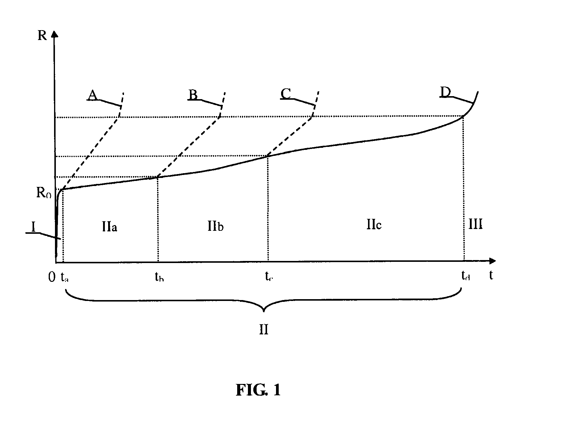
Concentration polarization and pore clogging generally occur several seconds or minutes after filtration starts.
The development of mineral scaling is slow; however, if the cake layer thickens rapidly, the filtering resistance will greatly increase again, which may even make the membrane to lose its water producing capability.
Membrane fouling is inevitable in use of membrane separation devices.
But it has no significant effect in controlling the development of the gel layer due to deposition of gel substances on the membrane surface, and has no effect at all in controlling pore clogging due to gels and small molecules.
Consequently, using solely forward hydraulic cleaning can not maintain a good cleaning effect in a long term.
Rapid development of membrane fouling can be controlled to a certain extent, however, this cleaning effect is limited and is achieved with increased power consumption for speeding up the cross flow and reduced operating time of the membrane, which result in increased operating costs of the system, more membrane separation devices to be configured, and increased construction costs of the system.
However, the gas, cleaning water or cleaning solution can not wash or soak the surface of the membrane that is in contact with the liquid to be filtered while the membrane is in its normal operation, where the gel layer and cake layer, as two major forms of membrane fouling, form and develop, thereby greatly degrading the filtering performance of the membrane.
Conventional reverse hydraulic cleaning and reverse chemical cleaning can only act on the other surface opposite to the surface of the membrane that is in contact with the liquid to be filtered while the membrane is in its normal operation, and therefore can not achieve a good cleaning effect.
Moreover, reverse hydraulic cleaning and reverse chemical cleaning generally use the membrane permeating liquid of the membrane separation device, i.e., the end product of the water treatment system, as the cleaning water or the solvent, which degrades the actual water producing capability of the membrane separation device to a certain extent, requires more membrane separation devices to meet a designated processing scale, and increases construction costs of the system.
However, said period of time is generally long, during which the membrane separation device can not operate normally, and the water treatment plant is put in a standby or halt state.
Meanwhile, reverse hydraulic cleaning or reverse chemical cleaning itself consumes a certain amount of the end product water.
Therefore, if this cleaning method is applied frequently, the actual utilization of the membrane separation device and the water producing rate of the system will be greatly reduced, and more membrane separation devices have to be configured to meet a designated processing scale, thereby increasing construction costs of the system.
And if this cleaning method is applied infrequently, then good filtering performance of the membrane separation device can not be maintained in a long term; and the duration of cleaning or the concentration of the chemical agent has to be extended or increased, otherwise, the filtering performance can not be thoroughly recovered.
This cleaning method involves too many steps, is not well-planned and uses too much cleaning solution and chemical agent, thereby restricting its applications in actual water treatment.

Method used


Image

  • Method and apparatus for cleaning a film seperating device
  • Method and apparatus for cleaning a film seperating device
  • Method and apparatus for cleaning a film seperating device

Examples


first embodiment

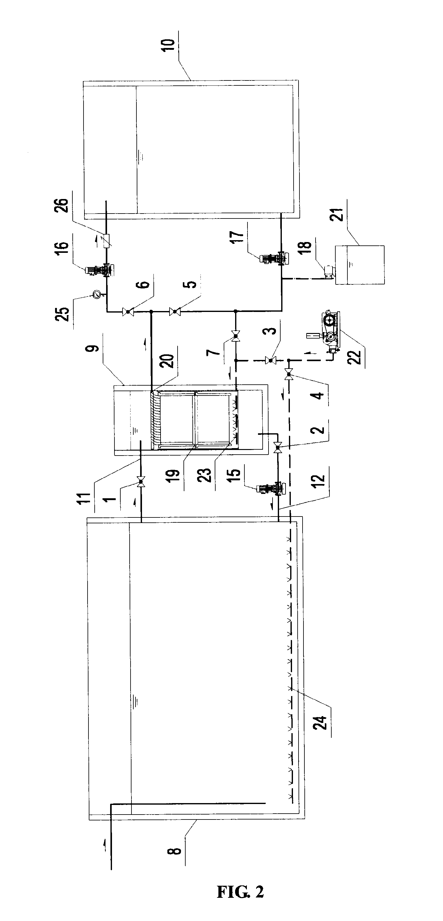
[0099]As shown in FIG. 2 and FIG. 4, as part of a membrane bioreactor based wastewater treatment system, an apparatus for cleaning a membrane separation device includes a bioreaction tank 8; a membrane filter tank 9 independent from the bioreaction tank 8 and having a wall shared with the bioreaction tank 8; a membrane separation device 19 arranged in the membrane filter tank 9; a membrane permeating liquid tank 10 for storing membrane permeating liquid of the membrane separation device 19; a feed-liquid supplying channel 11 for transmitting activated sludge mixed liquor in the bioreaction tank 8 to the membrane filter tank 9, and a feed-liquid supplying valve 1 installed in the feed-liquid supplying channel 11, where the feed-liquid supplying channel 11 passes through the sidewall of the bioreaction tank 8 at an upper part of the sidewall with the top of the channel being 400 mm lower than the liquid level inside, and passes through the sidewall of the membrane filter tank 9 at an ...

second embodiment

THE SECOND EMBODIMENT

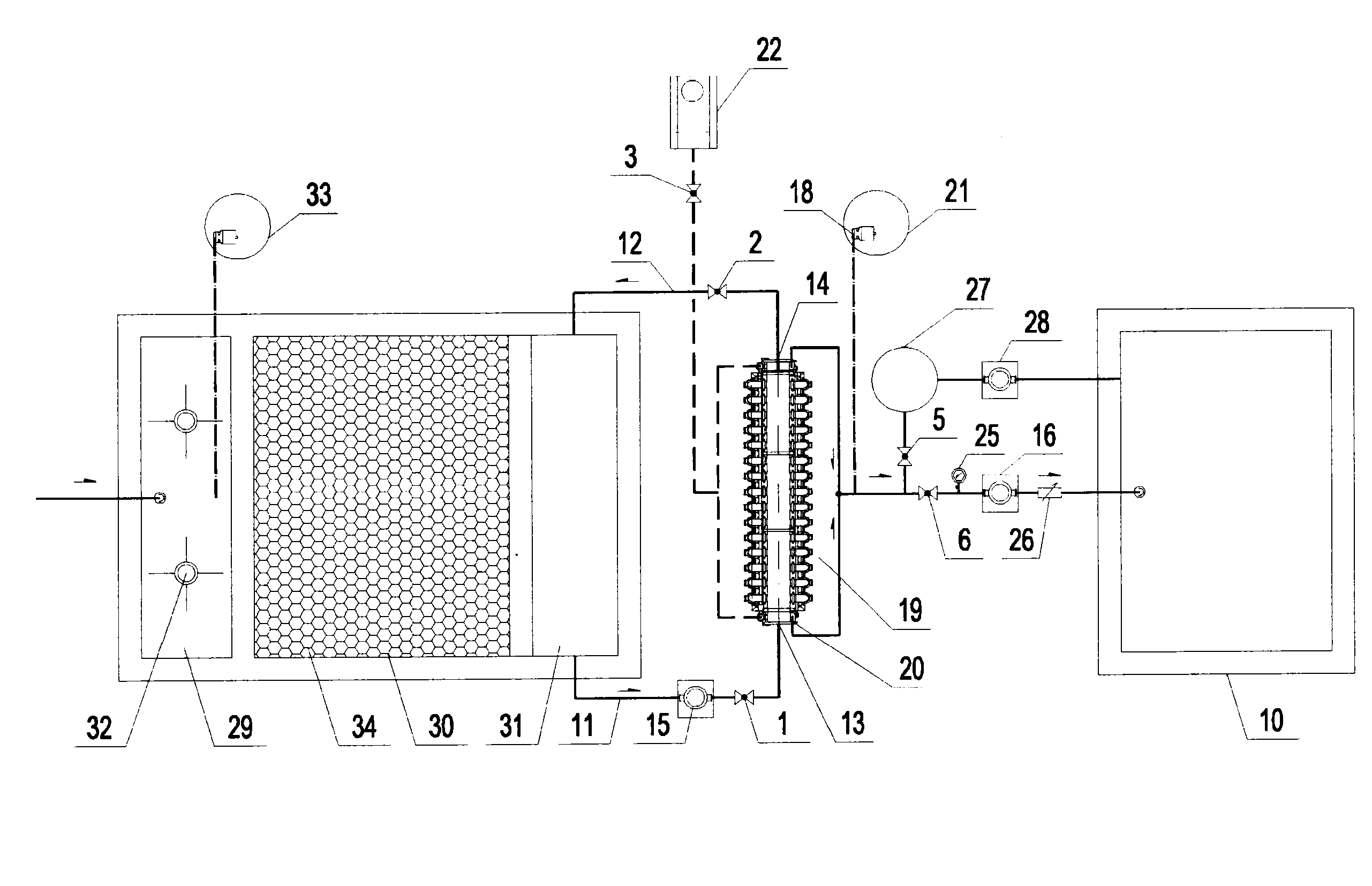
[0109]As shown in FIG. 3 and FIG. 5, as part of a drinking water treatment system, an apparatus for cleaning a membrane separation device includes a coagulation reaction tank 29; an inclined plate sedimentation tank 30; an intermediate water tank 31; a membrane separation device 19; a membrane permeating liquid tank 10; an stirrer 32 arranged in the coagulation reaction tank 29; an inclined plate 34 arranged in the inclined plate sedimentation tank 30; a feed-liquid supplying channel 11 for transmitting upper clear liquid in the intermediate water tank 31 to the membrane separation device 19 and a circulation pump 15 and a feed-liquid supplying valve 1 installed in the feed-liquid supplying channel 11, where the feed-liquid supplying channel 11 passes through the sidewall of the intermediate water tank 31 at a lower part of the sidewall with the top of the channel being 200 mm higher than the bottom of the tank; a feed-liquid backflow channel 12 for returning a ...


PUM


Abstract

A method for cleaning a film separating device involves: a) performing positive-direction water cleaning when the ratio between the film filter resistance and the preliminary film filter resistance is less than 1.2; b) performing reverse water cleaning when the ratio between the film filter resistance and the preliminary film filter resistance is greater-than or equal-to 1.2; c) performing reverse chemical cleaning when the ratio between the film filter resistance and the preliminary film filter resistance is greater-than or equal-to 2; d) performing positive-direction chemical cleaning when the ratio between the film filter resistance and the preliminary film filter resistance is greater-than or equal-to 3.

Description

PRIORITY CLAIM[0001]The present application is a National Phase entry of PCT Application No. PCT / CN2009 / 071687, filed May 8, 2009, which claims the priority to Chinese patent application No. 200810113983.4, filed with the Chinese Intellectual Property Office on May 30, 2008 and titled “Method and apparatus for cleaning membrane separation device”, the disclosures of which are hereby incorporated by reference in their entirety.FIELD OF THE INVENTION[0002]The present invention relates to the field of water treatment technologies and in particular to a method and an apparatus for cleaning a membrane separation device.BACKGROUND OF THE INVENTION[0003]With the development of membrane science and technology and the innovation of water treatment technologies in recent years, membrane separation technology and membrane separation devices based on membrane separation technology have been widely adopted in the field of water treatment. As their applications become more popular and manufacturi...

Claims


Application Information

Patent Timeline
Patent Type & Authority Applications(United States)
IPC IPC(8): B08B3/00
CPCB01D2321/16B01D2321/185B01D65/02B01D2321/164B01D2321/04B01D61/22B01D2321/02B01D61/18B01D2321/28
Inventor SUN, YOUFENG
Owner BEIJING ECOJOY WATER TECH
Learn More