

Tracking solar photovoltaic power generation system, and tracking control method and tracking shift correction method for tracking solar photovoltaic power generation system
- Summary
- Abstract
- Description
- Claims
- Application Information
AI Technical Summary
Benefits of technology
Problems solved by technology
Method used
Image

Examples
embodiment 1
[0122]First is a description of a tracking control method for a tracking solar photovoltaic power generation system according to Embodiment 1, given with reference to FIGS. 1 to 3.
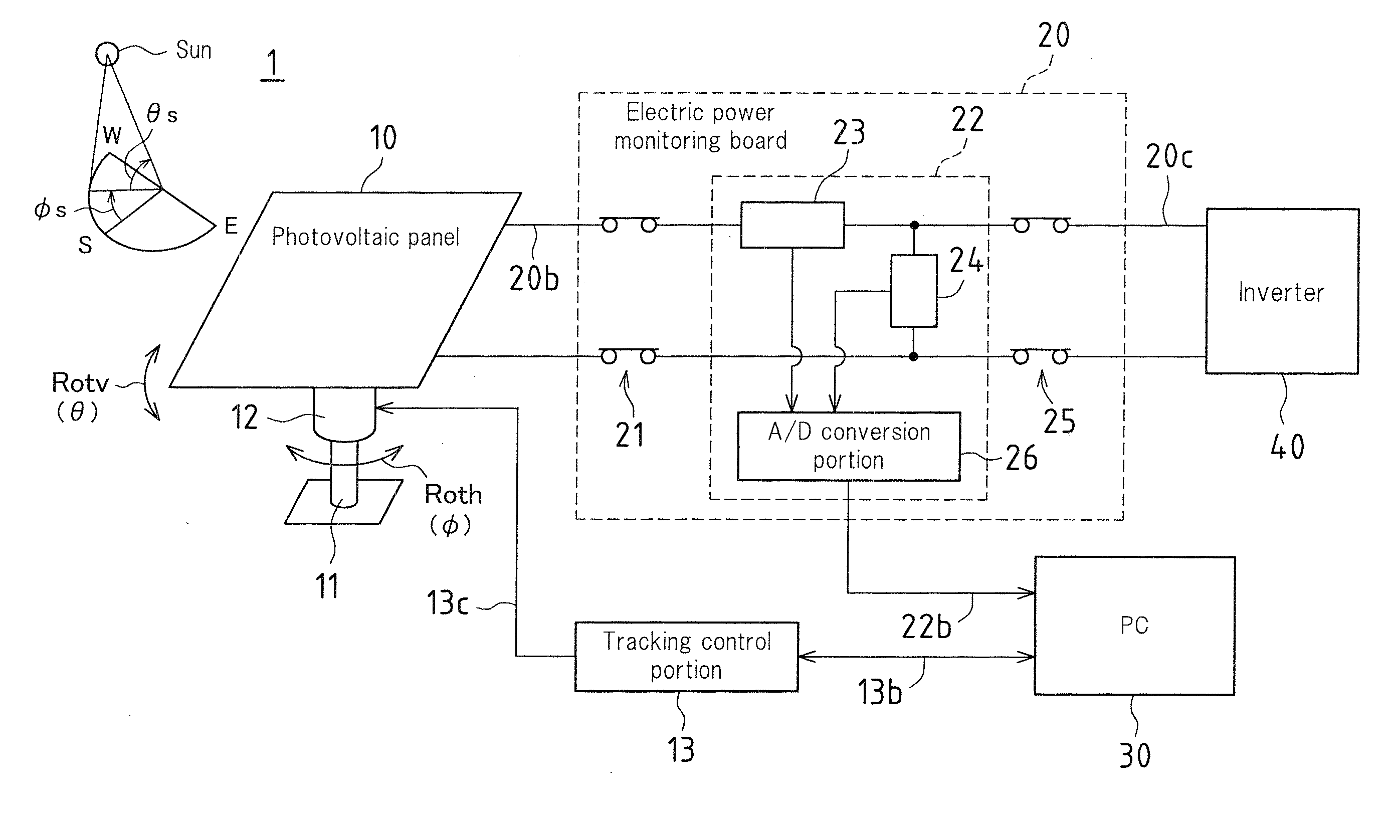
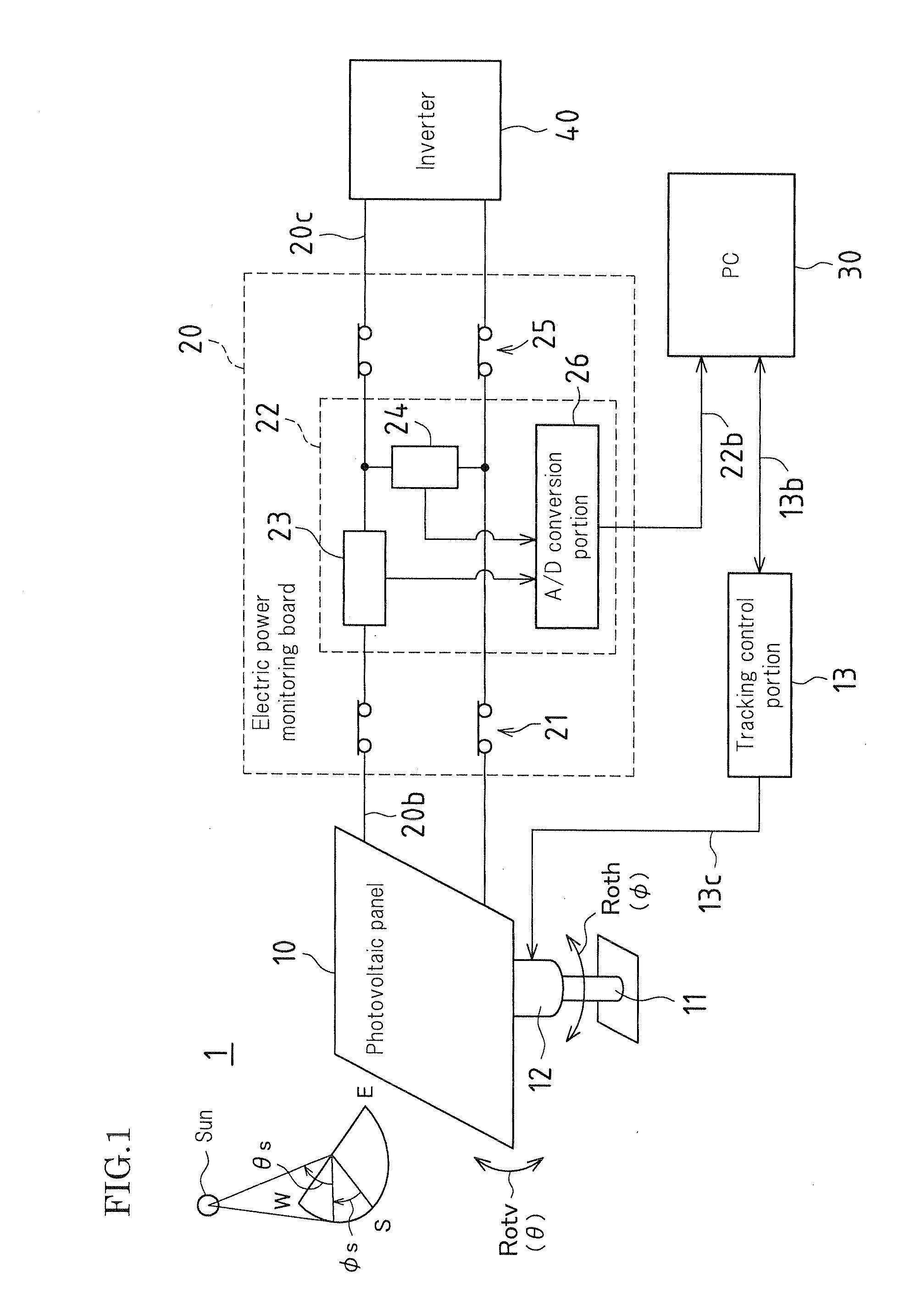
[0123]FIG. 1 is a block diagram illustrating a schematic configuration of the tracking solar photovoltaic power generation system according to Embodiment 1.
[0124]In the tracking control method for the tracking solar photovoltaic power generation system according to the present embodiment, a tracking drive solar photovoltaic power generator 1 includes a photovoltaic panel 10 that converts sunlight into electric power, and a tracking control portion 13 that provides tracking control over the turning position and tilt position of the photovoltaic panel 10 so that the photovoltaic panel 10 can track the solar trajectory based on a turning coordinate φ (turning direction Roth) and a tilt coordinate θ (tilt direction Rotv) that have been set corresponding to a solar azimuth angle φs and a solar altitude θs.
[0125...
second embodiment
[0151]Next is a description of a tracking control method (tracking control method adopting a positional shift detection / correction program) for a tracking solar photovoltaic power generation system according to Embodiment 2 of the present invention, given with reference to FIGS. 4 to 6.
[0152]FIG. 4 is a flowchart showing the procedure performed according to a first operation pattern when detecting and correcting a shift in the position of a tracking drive solar photovoltaic power generator in accordance with the tracking control method for the tracking solar photovoltaic power generation system according to Embodiment 2. FIG. 5A is a reference chart containing detailed information about the transition of the control coordinates according to the first operation pattern shown in FIG. 4, and FIG. 5B is an explanatory chart containing footnotes to FIG. 5A. FIG. 6 is a coordinate diagram plotting the transition of the control coordinates according to the first operation pattern shown in ...
third embodiment
[0221]Next is a description of a tracking control method for a tracking solar photovoltaic power generation system (tracking control method adopting a positional shift detection / correction program) according to Embodiment 3 of the present invention, given with reference to FIGS. 7 to 9.
[0222]FIG. 7 is a flowchart showing the procedure performed according to the second operation pattern when detecting and correcting a shift in the position of a tracking drive solar photovoltaic power generator in accordance with the tracking control method for the tracking solar photovoltaic power generation system according to Embodiment 3. FIG. 8A is a reference chart containing detailed information about the transition of the control coordinates according to the second operation pattern shown in FIG. 7, and FIG. 8B is an explanatory chart containing footnotes to FIG. 8A. FIG. 9 is a coordinate diagram plotting the transition of the control coordinates according to the second operation pattern show...
PUM
 Abstract
Description
Claims
Application Information