Device and Method for Transporting Heat

a technology of heat transport and device, applied in the direction of moving conduit heat exchanger, stationary tubular conduit assembly, lighting and heating apparatus, etc., can solve the problems of reducing efficiency, high velocity created in fluid, large friction and turbulence, etc., and achieves less complex, higher efficiency, and greater flexibility

Active Publication Date: 2011-03-24
ROTOBOOST AS
View PDF9 Cites 0 Cited by
  • Summary
  • Abstract
  • Description
  • Claims
  • Application Information

AI Technical Summary

Benefits of technology

[0009]In the present invention efficiency is enhanced among other in that the inlet and outlet are primarily at the rotation axis where the fluid is transported to / from the periphery through channels, and in that there may be more than two fluids wherein at least one of them is compressible to provide heat. A compressible fluid may exchange heat directly with another incompressible fluid in fog-form outward to the periphery. The rotation device is mounted in bearings in a surrounding evacuated housing with sealing.

Problems solved by technology

As the pressure difference is large between the inside and outside of said nozzles at the periphery, a high velocity is created in the fluid, with corresponding large friction and turbulence.
The result of the said will reduce the efficiency.
This will reduce cooling efficiency.
This will also result in bad flexibility.

Method used


Image

  • Device and Method for Transporting Heat
  • Device and Method for Transporting Heat

Examples


example 1

[0044]The calculation below shows an example of theoretical temperatures for Hydrogen and Argon in a closed system with heat exchanging at the periphery, and at a peripheral speed (vp) 400 m / s. 1=inlet. 2=periphery. 3=outlet. As the flow-speed in the fluid channels can be relatively low, is resistance, pressure and temperature fall in a few percentages, and thus are neglected.

ΔT 1−2=ΔT 3−2 With same cp. (cp=heat capacity at constant pressure)

vp=400 m / s, cp h2=14320 J / kg K, cp Ar=520 J / kg K

ΔT h2(1−2)=vp2 / (2×cp)=4002 m / s / (2×14320 J / kg K)=5.6 K

ΔT Ar(1−2)=vp2 / (2×cp)=4002 m / s / (2×520 J / kg K)=154 K

[0045]At the same mass cp maximal heat exchange in T is equal to:

T=(((ΔAr−(ΔTh2×cp masse Ar) / (cp masse h2))) / 2=(154K−5.6K) / 2=74.2 K

[0046]This means that the h2 can be delivered 74.2 K warmer than the ambient from its heat exchanger on one shaft end, and on the other shaft end the argon is 74.2 K colder in its heat exchanger than the ambient.

example 2

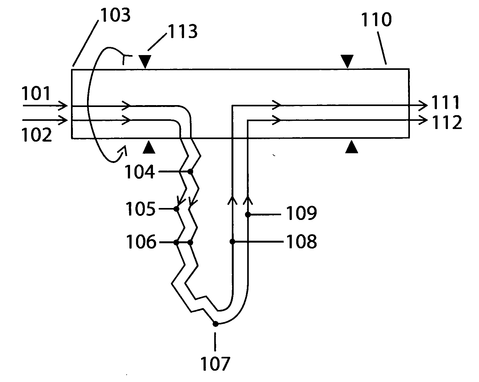
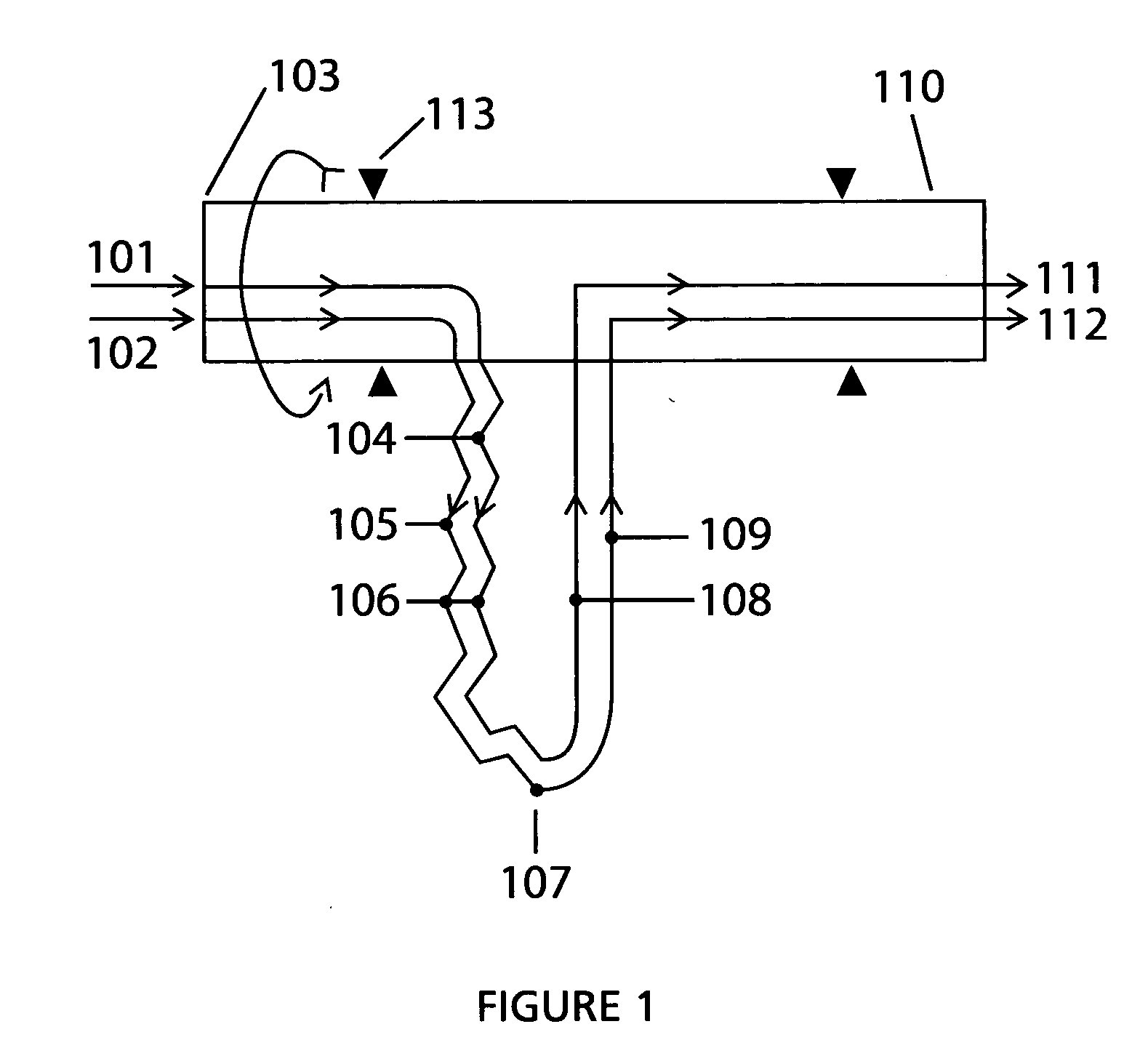
[0047]By using air as a heating fluid in an open system as a heat exchanger to argon as the cooling fluid pressurized in a closed circuit with twice the mass cp=(1000×2 kJ / kg K) / (520 kJ K)=3.85 in heat exchanger 106.

vp=400 m / s, cp luft=1000 J / kg K, cp Ar=520 J / kg K

ΔT Ar(1−2)=vp2 / (2×cp)=4002 m / s / (2×520 J / kg K)=154 K

ΔT air(1−2)=vp2 / (2×cp)=4002 m / s / (2×1000 J / kg K)=80 K

±ΔT=(((ΔAr−(ΔT luft×cp mass air) / (cp mass Ar))) / 2

±ΔT=(((154K−(80K×1000 J / kg K) / (3.85×520 J / kg K))) / 2=57K

[0048]This means that the air is 57K warmer than the ambient and the Argon is 57 k colder than ambient at outlet in its heat exchanger, and the airs have to be supplied pressurized to periphery for heating.

[0049]But if the air under constant pressure is cooled by argon through its heat exchanger at or outside the outlet, will both air and argon have little more T as the ambient and the air is supplied pressurized to the environment's T. And at a isentropic exponent (k)=1.4. And T ambient air=291 K and 1 bar. Will then t...


PUM


Abstract

It is a purpose for the invention to provide a rotating device (107) to generate heat, cold and pressure from the outlet at the rotation axis, by centrifugation pressurized fluid in that it include at least two under-supported U-channel structures (107) where one of the channels (104, 105) from each U-channel structure (107) toward the periphery (107) is in thermal contact, forming a heat exchanger (106) where one of the channels (105) contains a compressible cooling fluid which develops heat from the centrifugal compression in the channel (105), and the heat is transferred to a heating fluid with a lower temperature in the second channel (104) in heat exchanger (106) toward the periphery (107) where heat exchanging ceases, and the U-channels (107) is connected to its inlet—(101, 102) and outlet channels (111, 112) at the rotation axis for the transport of said fluid through the U-channels (104, 105, 108, 109) via the periphery (107), which after the outlet (111) for heating fluid is heat-exploited, and cooling fluid (112) is cold-exploited, and the heating fluid before the outlet (111) is pressurized by the heat received in the heat exchangers (106), and the cooling fluid is compressed with an adapted circulation pressure before inlet (102) to compensate against emitted heat in heat exchangers (106), and an expansion work of the heating fluid reduces the supplied energy to the compression work of the cooling fluid, and U-channel structures is rotated by appropriate means, and the U-channels are arranged radial and in balance around the rotation axis.

Description

FIELD OF THE INVENTION[0001]The present invention relates to generation of heat in a pressurized fluid by means of centrifugal force.TECHNICAL BACKGROUND[0002]There are known devices which are rotating in order to utilize the centrifugal force to compress a fluid, which then is heated and deliver the heat to another fluid or medium at the periphery of the device.[0003]Common for these devices is that one of the fluids drive the device via nozzles located at the periphery and that the fluid is transported through the device only by centrifugal force.[0004]As the pressure difference is large between the inside and outside of said nozzles at the periphery, a high velocity is created in the fluid, with corresponding large friction and turbulence. In case the nozzles are turned backward in the direction of rotation, this will that also create rotation resistance and friction. The result of the said will reduce the efficiency.[0005]When the fluid is a gas that is relatively moist; the gas...

Claims


Application Information

Patent Timeline
Patent Type & Authority Applications(United States)
IPC IPC(8): F28F1/00
CPCF25B3/00F28D7/0016F28D11/04F25B9/00
Inventor SKOMSVOLD, AGE JORGEN
Owner ROTOBOOST AS
Why Eureka
Try Eureka