
Power electronic devices, methods of manufacturing the same, and integrated circuit modules including the same

a technology of power electronic devices and manufacturing methods, applied in the field of power electronic devices, can solve the problems of increasing the complexity of the manufacturing process, the problem of 2deg channels, etc., and achieve the effect of simple process

Active Publication Date: 2011-03-24
SAMSUNG ELECTRONICS CO LTD
View PDF17 Cites 16 Cited by
  • Summary
  • Abstract
  • Description
  • Claims
  • Application Information

AI Technical Summary

Benefits of technology

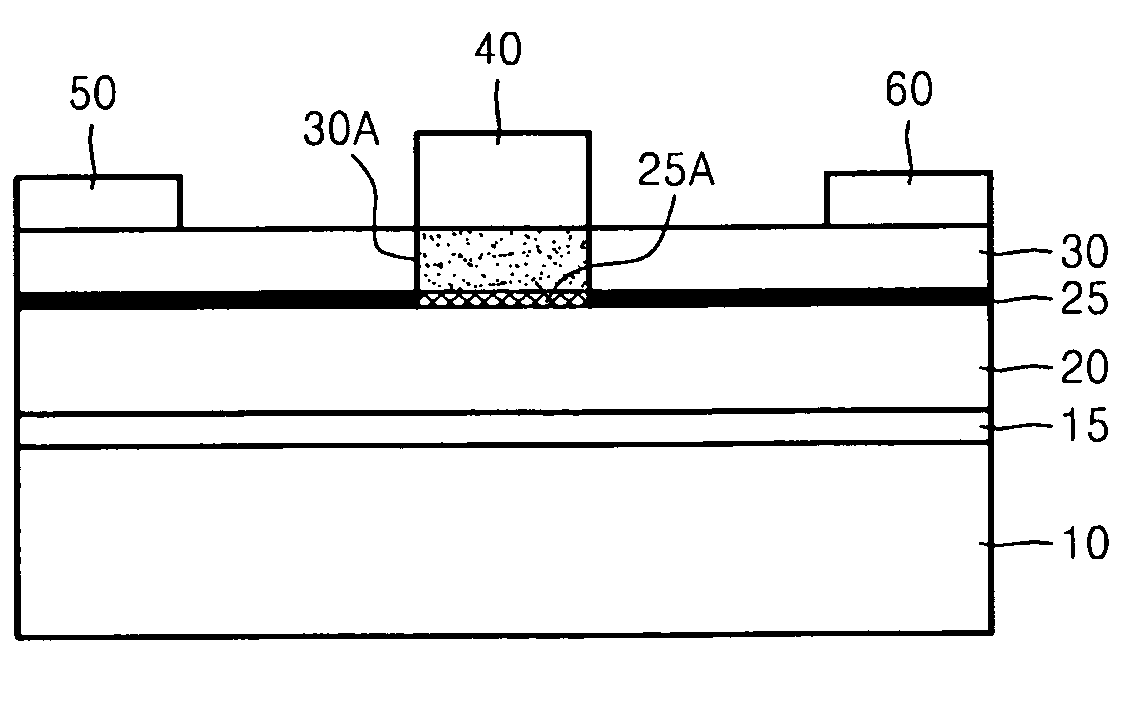
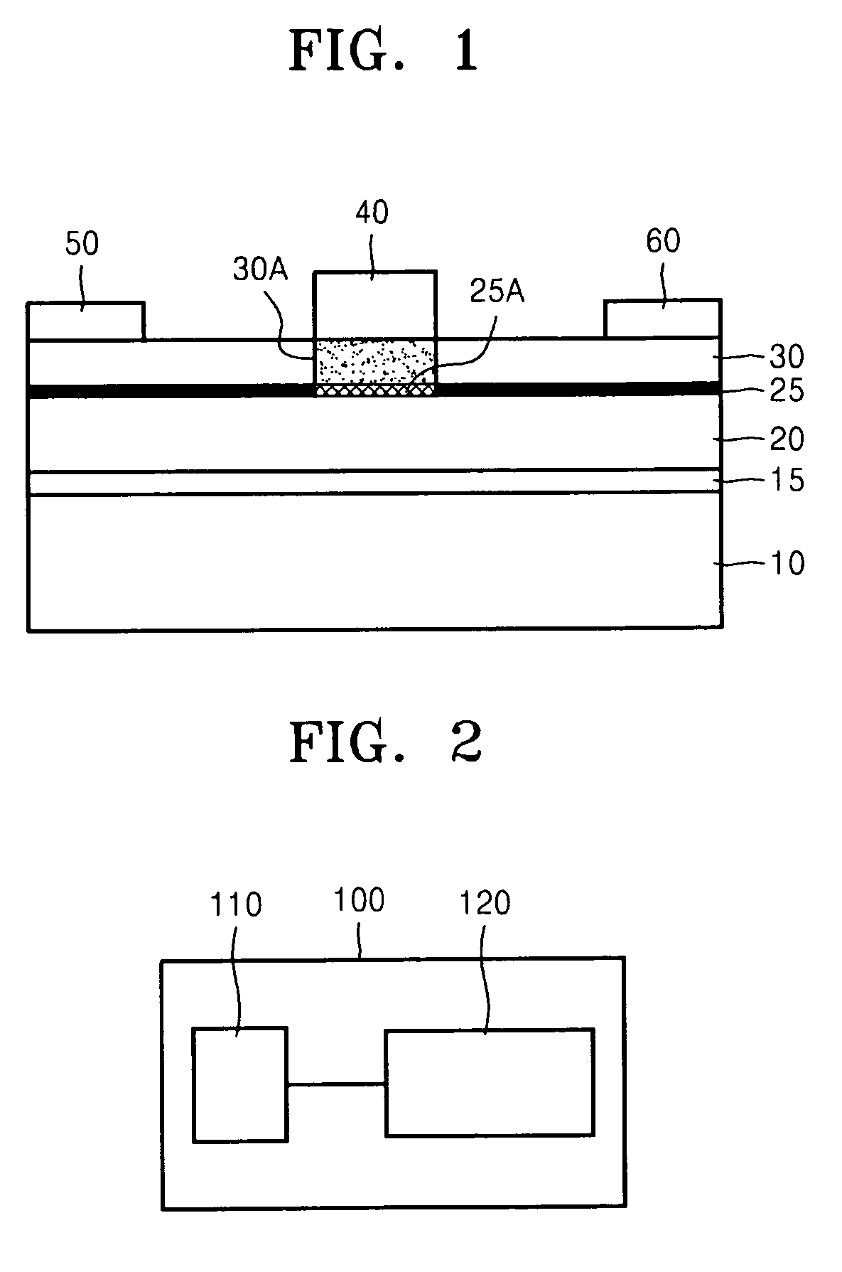
[0008]Example embodiments may provide power electronic devices including a region of a 2-dimensional electron gas (2DEG) channel in a normally-off state. A normally-off state may be achieved without etching a portion of a material layer for forming the 2DEG channel and / or forming an additional material layer. Example embodiments may provide methods of manufacturing the power electronic devices using a simple process. Example embodiments may provide integrated circuit (IC) modules including the power electronic devices.
[0011]The entire upper semiconductor layer may be continuous and may have a uniform thickness. The upper semiconductor layer under the gate may contain an impurity for reducing the lattice constant difference between the lower and upper semiconductor layers. The impurity may be an element that belongs to the same group in a periodic table as a main component element of the lower and upper semiconductor layers, and may have a larger atomic number than the main component element. Each of the lower and upper semiconductor layers may contain a Group III-V compound semiconductor.

Problems solved by technology

A 2DEG channel may be problematic as a 2DEG channel may be in a ‘normally-on’ state (e.g., depletion mode HFET).
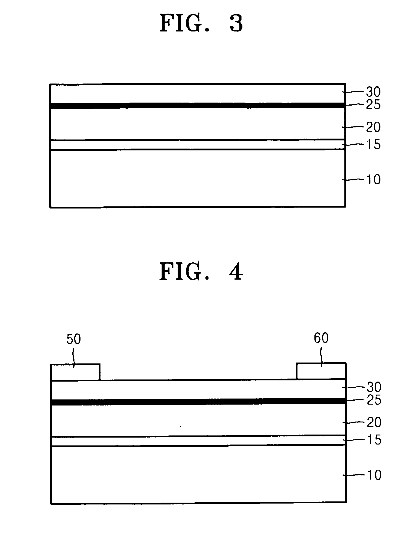
However, because methods of forming a 2DEG channel to be in a normally-off state may include etching a material layer for forming a 2DEG channel of a HFET and then filling the etched portion with a material, or forming an additional material layer on the 2DEG channel, the methods may increase the complexity of a HFET manufacturing process.

Method used


Image

  • Power electronic devices, methods of manufacturing the same, and integrated circuit modules including the same
  • Power electronic devices, methods of manufacturing the same, and integrated circuit modules including the same
  • Power electronic devices, methods of manufacturing the same, and integrated circuit modules including the same

Examples


Embodiment Construction

[0021]Example embodiments will now be described more fully with reference to the accompanying drawings, in which example embodiments are shown. Example embodiments may, however, be embodied in many different forms and should not be construed as being limited to the embodiments set forth herein; rather, these embodiments are provided so that this disclosure will be thorough and complete, and will fully convey the concept of example embodiments to those of ordinary skill in the art. In the drawings, the thicknesses of layers and regions are exaggerated for clarity. Like reference numerals in the drawings denote like elements, and thus their description will be omitted.

[0022]It will be understood that when an element is referred to as being “connected” or “coupled” to another element, it can be directly connected or coupled to the other element or intervening elements may be present. In contrast, when an element is referred to as being “directly connected” or “directly coupled” to anot...


PUM


Abstract

Power electronic devices including 2-dimensional electron gas (2DEG) channels and methods of manufacturing the same. A power electronic device includes lower and upper material layers for forming a 2DEG channel, and a gate contacting an upper surface of the upper material layer. A region below the gate of the 2DEG channel is an off region where the density of a 2DEG is reduced or zero. The entire upper material layer may be continuous and may have a uniform thickness. A region of the upper material layer under the gate contains an impurity for reducing or eliminating a lattice constant difference between the lower and upper material layers.

Description

CROSS-REFERENCE TO RELATED APPLICATION[0001]This application claims priority under 35 U.S.C. §119 to Korean Patent Application No. 10-2009-0090561, filed on Sep. 24, 2009, in the Korean Intellectual Property Office (KIPO), the entire contents of which is incorporated herein by reference.BACKGROUND[0002]1. Field[0003]Example embodiments relate to electronic devices, and more particularly, to power electronic devices including a 2-dimensional electron gas (2DEG) channel, methods of manufacturing the same, and integrated circuit (IC) modules including the same.[0004]2. Description of the Related Art[0005]A heterojunction field effect transistor (HFET), also known as a high electron mobility transistor (HEMT), is an example of a power electronic device. A HFET may be used in high voltage devices, and may have a high breakdown voltage, high thermal conductivity, a large saturated electron drift velocity, a high power density and a small size. A HFET with a high breakdown voltage may incl...

Claims


Application Information

Patent Timeline
Patent Type & Authority Applications(United States)
IPC IPC(8): H01L29/778H01L21/335
CPCH01L29/2003H01L29/7787H01L29/66462H01L29/207
Inventor KIM, JONG-SEOBHONG, KI-HAOH, JAE-JOONCHOI, HYUK-SOONWHANG, IN-JUNSHIN, JAI-KWANG
Owner SAMSUNG ELECTRONICS CO LTD
Learn More