Check patentability & draft patents in minutes with Patsnap Eureka AI!

Fluctuation oscillator, fluctuation oscillating system, observation device and control system

a technology of fluctuation oscillator and oscillator, which is applied in the direction of pulse generator, pulse technique, instruments, etc., can solve the problems of difficult to achieve a cpg with low power consumption, and inconvenient use of oscillator, etc., and achieve the effect of low power consumption

Active Publication Date: 2011-03-24
OSAKA UNIV
View PDF2 Cites 9 Cited by
  • Summary
  • Abstract
  • Description
  • Claims
  • Application Information

AI Technical Summary

Benefits of technology

The present invention provides a fluctuation oscillator and a fluctuation oscillating system that have low power consumption, are robust against noise signals, and can change the oscillation frequency flexibly and autonomously. The fluctuation oscillator includes a plurality of stochastic resonators that apply fluctuation to an input signal by superimposing a noise signal thereon, compare the resulting signal with a threshold value, and then perform differentiation to output a pulse signal. The fluctuation oscillating system includes two fluctuation oscillators that are coupled unidirectionally in a ring-like form. The observation device and control system according to the present invention use the fluctuation oscillator described above.

Problems solved by technology

However, in order to create a CPG artificially by computer simulation, it is necessary to use a computer with high computing capacity, and there has been a problem in that compactification of the apparatus and reduction of power consumption are difficult to achieve.
Furthermore, in the method described in Non-Patent Document 1, a conventional oscillator is instable in respect of noise, and moreover, the drive voltage of the semiconductor elements must be set to a high level in order to combat noise, thus making it difficult to achieve a CPG with low power consumption.
Moreover, in a conventional oscillator, the oscillation frequency is fixed by the circuit constant, and since the oscillation frequency cannot be changed flexibly and autonomously, then there has been a problem in that such an oscillator is not suitable as a CPG which is required to perform cooperative operation between oscillators.

Method used


Image

  • Fluctuation oscillator, fluctuation oscillating system, observation device and control system
  • Fluctuation oscillator, fluctuation oscillating system, observation device and control system
  • Fluctuation oscillator, fluctuation oscillating system, observation device and control system

Examples


Embodiment Construction

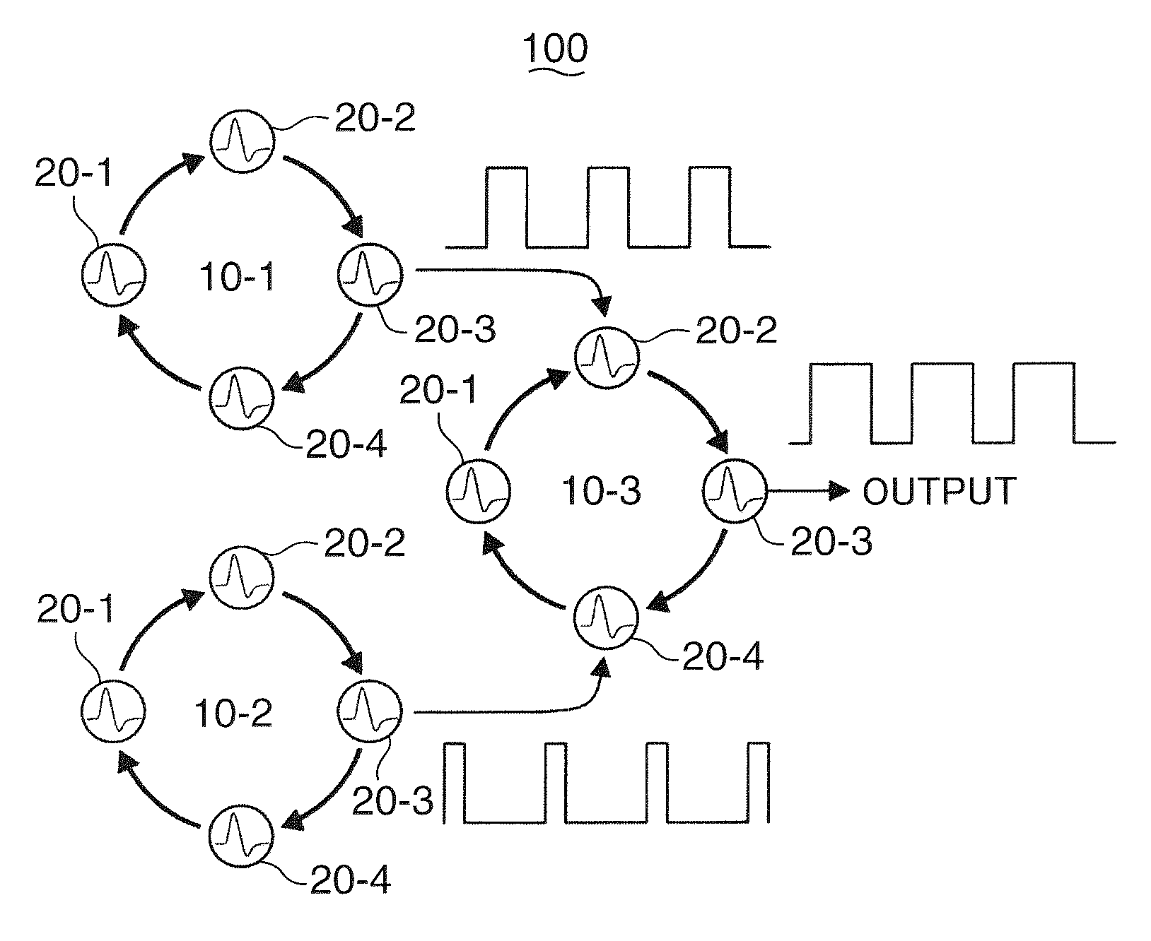
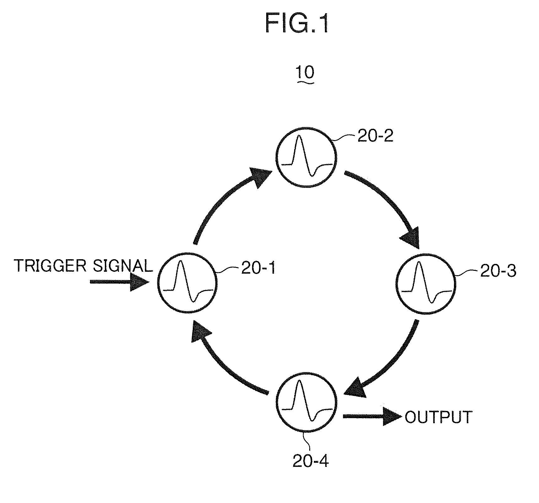
[0042]Below, a fluctuation oscillator according to an embodiment of the present invention will be described. FIG. 1 shows a general schematic drawing of a fluctuation oscillator 10 according to an embodiment of the present invention. The present fluctuation oscillator 10 comprises four stochastic resonators 20-1 to 20-4 which are coupled unidirectionally in a ring-like form. Where a certain stochastic resonator is not specified in particular, reference is made simply to stochastic resonator(s) 20. Furthermore, the number of stochastic resonators 20 is not limited to four, and may be two, three or five or more.

[0043]Here, unidirectional coupling means that the signals flow in one direction. In the case of FIG. 1, the stochastic resonators 20 are connected in a ring-like form by means of the output terminal of one stochastic resonator being connected to the input terminal of another adjacent stochastic resonator 20 and the input terminal of one stochastic resonator 20 being connected ...


PUM


Abstract

Four stochastic resonators 20-1 to 20-4 outputting a pulse signal in accordance with a stochastic resonance phenomenon are unidirectionally coupled in a ring-like form to constitute a fluctuation oscillator 10. When a signal output from each of the stochastic resonators 20-1 to 20-4 is successively transmitted in the stochastic resonators 20-1 to 20-4 coupled in a ring-like form, the output timings at each stochastic resonator 20 are synchronized with each other due to a cooperation phenomenon between the stochastic resonators 20-1 to 20-4, so that each stochastic resonator 20 is self-excited to oscillate at a constant period of time.

Description

BACKGROUND OF THE INVENTION[0001]1. Field of the Invention[0002]The present invention relates to a fluctuation oscillator, a fluctuation oscillating system, an observation device and a control system.[0003]2. Description of the Related Art[0004]In recent years, various research has been carried out into artificially creating a central pattern generator (CPG) and using this CPG to operate actuators so as to control an object. Here, a CPG is an oscillator based on a neural network which autonomously outputs a periodic signal to the musculoskeletal system which controls the activities of walking, respiratory and circulatory organs, and the like, in a living organism. Known methods of artificially creating a CPG are a method which creates a CPG signal by computer simulation, and a method which joins together conventional oscillators, such as liquid crystal oscillators, Hartley oscillators, Clapp oscillators, astable multivibrators, in a plurality of chains, and the like. For example, SC...

Claims


Application Information

Patent Timeline
Patent Type & Authority Applications(United States)
IPC IPC(8): H03K3/03
CPCH03K3/0315G06G7/12
Inventor HOTTA, YASUSHIKANKI, TERUOASAKAWA, NAOKIKAWAHARA, TOSHIOKAWAI, TOMOJITABATA, HITOSHI
Owner OSAKA UNIV
Features
  • R&D
  • Intellectual Property
  • Life Sciences
  • Materials
  • Tech Scout
  • Unparalleled Data Quality
  • Higher Quality Content
  • 60% Fewer Hallucinations
Learn More