Eureka AIR delivers breakthrough ideas for toughest innovation challenges, trusted by R&D personnel around the world.

Thin layer fixed bed reactor for the chemical treatment of a finely divided catalytic solid

Active Publication Date: 2011-03-24
ENI +1
View PDF8 Cites 8 Cited by
  • Summary
  • Abstract
  • Description
  • Claims
  • Application Information

AI Technical Summary

Benefits of technology

[0071]The operating temperature is in the range 200° C. to 500° C., preferably in the range 300° C. to 450° C., and more preferably in the range 350° C. to 400° C.
[0072]It should be noted that the temperature changes during the catalyst reducti

Problems solved by technology

However, a fluidized bed reactor is not very well suited to reduction of a Fischer-Tropsch synthesis catalyst using hydrogen.
Further, in the case of a fluidized bed, dilution of the reagent by an inert gas which participates in fluidization is very rapidly limited by the rate of entrainment of the smallest particles of solid.
Finally, fluidized bed reactors may in some cases exhibit difficulties as regards good distribution of gas, except for using distribution systems which cause large pressure drops.

Method used


Image

  • Thin layer fixed bed reactor for the chemical treatment of a finely divided catalytic solid
  • Thin layer fixed bed reactor for the chemical treatment of a finely divided catalytic solid
  • Thin layer fixed bed reactor for the chemical treatment of a finely divided catalytic solid

Examples


Embodiment Construction

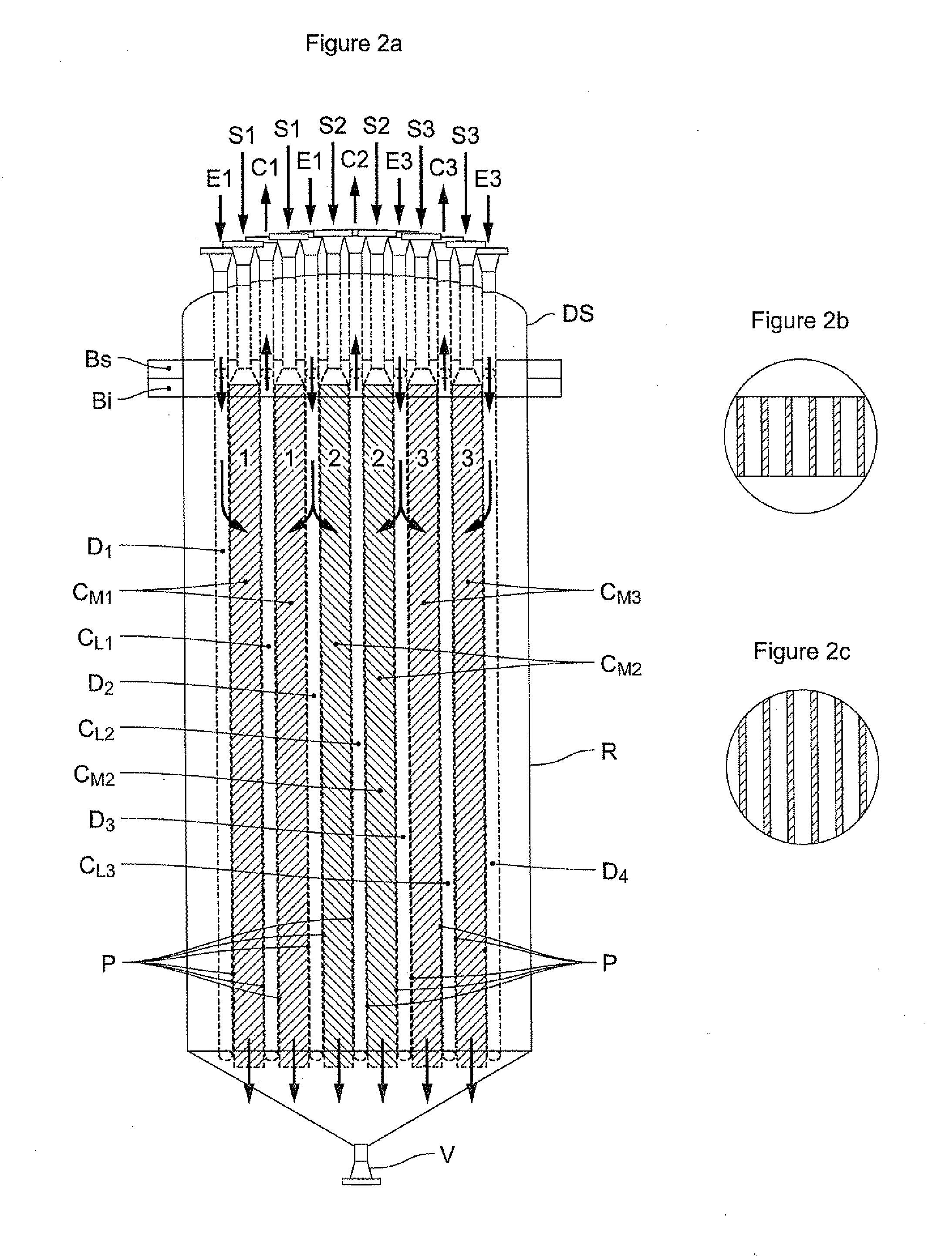
[0091]The description below is made with reference to FIGS. 2a, 2b, 2c corresponding to a planar configuration.

[0092]The present invention consists of a fixed bed reactor with thin layers constituted by an assembly of similar modules M functioning in parallel and enclosed in a common vessel constituting the envelope R of said reactor,

[0093]In the present particular case, the modules are identical.

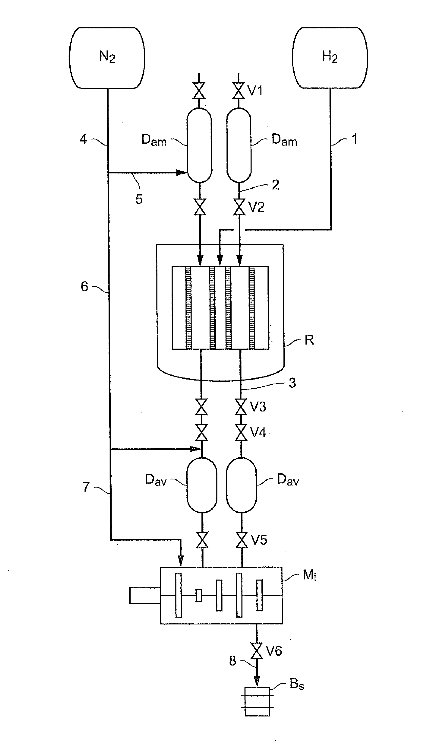
[0094]This reactor is intended to carry out a treatment on a catalytic solid present in the reactor in the form of fine particles generally with a diameter in the range 30 to 100 microns.

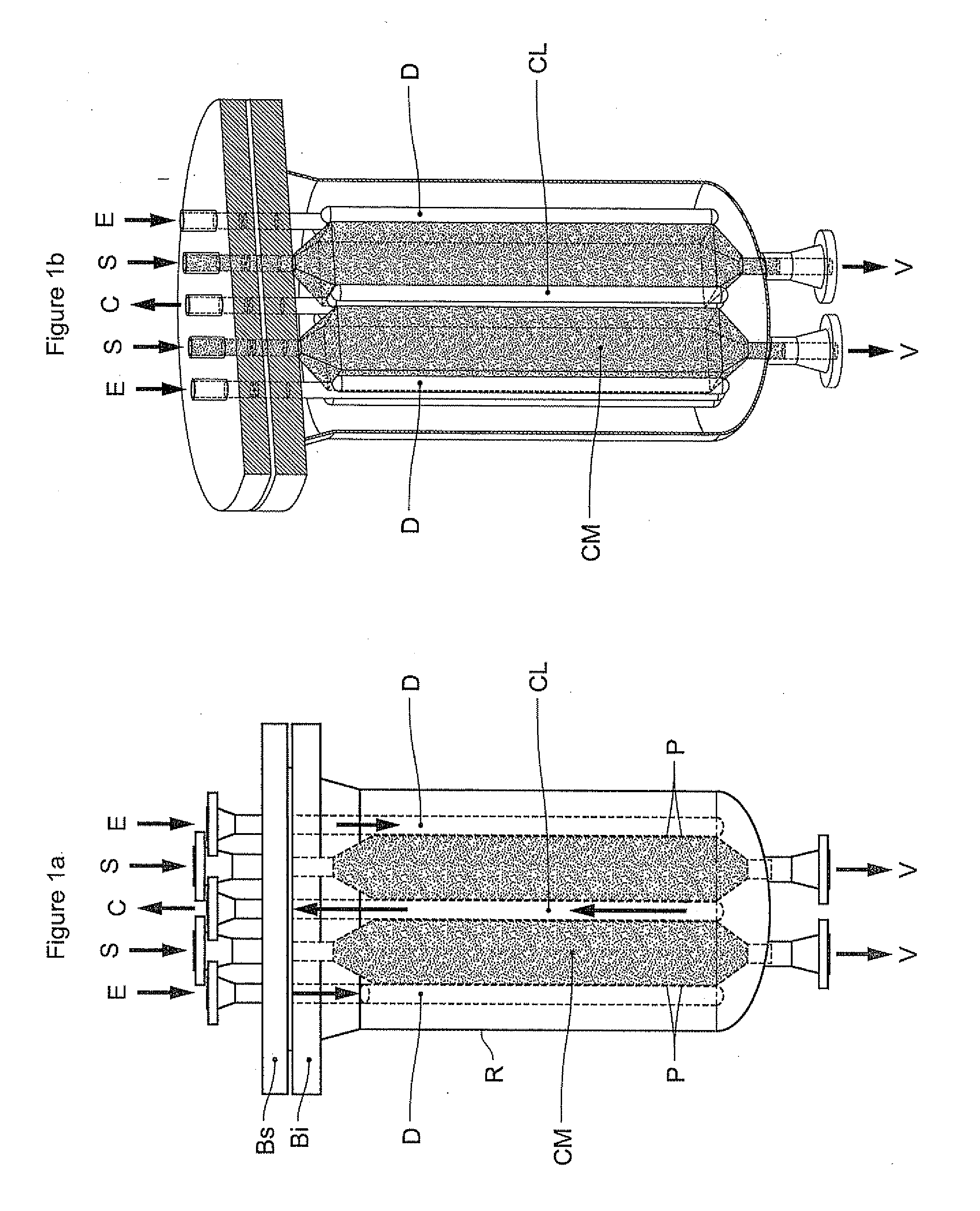
[0095]This treatment, which the skilled person generally terms reduction, uses a reagent gas which is hydrogen, optionally diluted with an inert gas, generally nitrogen, in any dilution but preferably being between 25% to 35% by volume. Each module M of the reactor is constituted by an assembly comprising:[0096]at least one partially porous envelope P enclosing each thin layer CM of particles to be treated ...


PUM

PropertyMeasurementUnit
Temperatureaaaaaaaaaa

Abstract

The present invention describes a thin layer fixed bed reactor intended for chemical treatments, in particular reduction of a Fischer-Tropsch synthesis catalyst. The reactor is designed in the form of similar, compact modules and operates with a ratio of linear pressure drop to outlet pressure which falls within certain limits.

Description

FIELD OF THE INVENTION[0001]The present invention relates to a thin layer fixed bed reactor intended to carry out chemical reactions of oxidation or reduction of divided solids (extrudates, beads or powders) used as catalysts or catalyst precursors in refining or petrochemical processes.[0002]More particularly, the present invention may be applied to reduction by hydrogen of a Fischer-Tropsch synthesis catalyst based on cobalt for use in the liquid phase.[0003]The Fischer-Tropsch synthesis catalyst is generally constituted by fine solid particles with a diameter in the range 30 to 100 micrometres (or microns, abbreviated to μm in the remainder of the text).[0004]Said catalyst is generally in its oxide form (CO3O4) following synthesis. Thus, a step for reduction should be carried out before using the catalyst in the Fischer-Tropsch synthesis reactor.[0005]This reduction step is carried out using a reducing gas which is pure hydrogen or hydrogen diluted in an inert gas.[0006]The prese...

Claims


Application Information

Patent Timeline
IPC IPC(8): C01G51/04B01J8/02
CPCB01J8/009B01J8/0278B01J8/0207B01J8/065B01J8/12B01J23/75B01J35/023B01J37/18B01J2208/022B01J2219/00031B01J2219/185B01J2219/1923C10G2/32C10G2300/703B01J8/0214B01J2208/021C10G2/34B01J8/02B01J35/40
Inventor DOUZIECH, DAMIENCAUSSE, GILLESCAPRANI, ERICVIGUIE, JEAN CHRISTOPHESCHWEITZER, JEAN MARCFORRET, ANN
Owner ENI
Why Eureka
Eureka Blog
Learn More