
Heat pump apparatus

Active Publication Date: 2011-03-31
FUJITSU GENERAL LTD
View PDF12 Cites 10 Cited by
  • Summary
  • Abstract
  • Description
  • Claims
  • Application Information

AI Technical Summary

Benefits of technology

[0008]Illustrative aspects of the present invention provide a heat pump apparatus which can exert high heating ability, and can be operated at high coefficient of performance, irrespective of whether or not liquid refrigerant is injected.

Problems solved by technology

When the expansion valve is controlled so as to obtain the objective SC value at the time when the injection is not executed, the COP is deteriorated and the operation at the high coefficient of performance is unable to be continued.

Method used


Image

  • Heat pump apparatus
  • Heat pump apparatus
  • Heat pump apparatus

Examples


exemplary embodiment 1

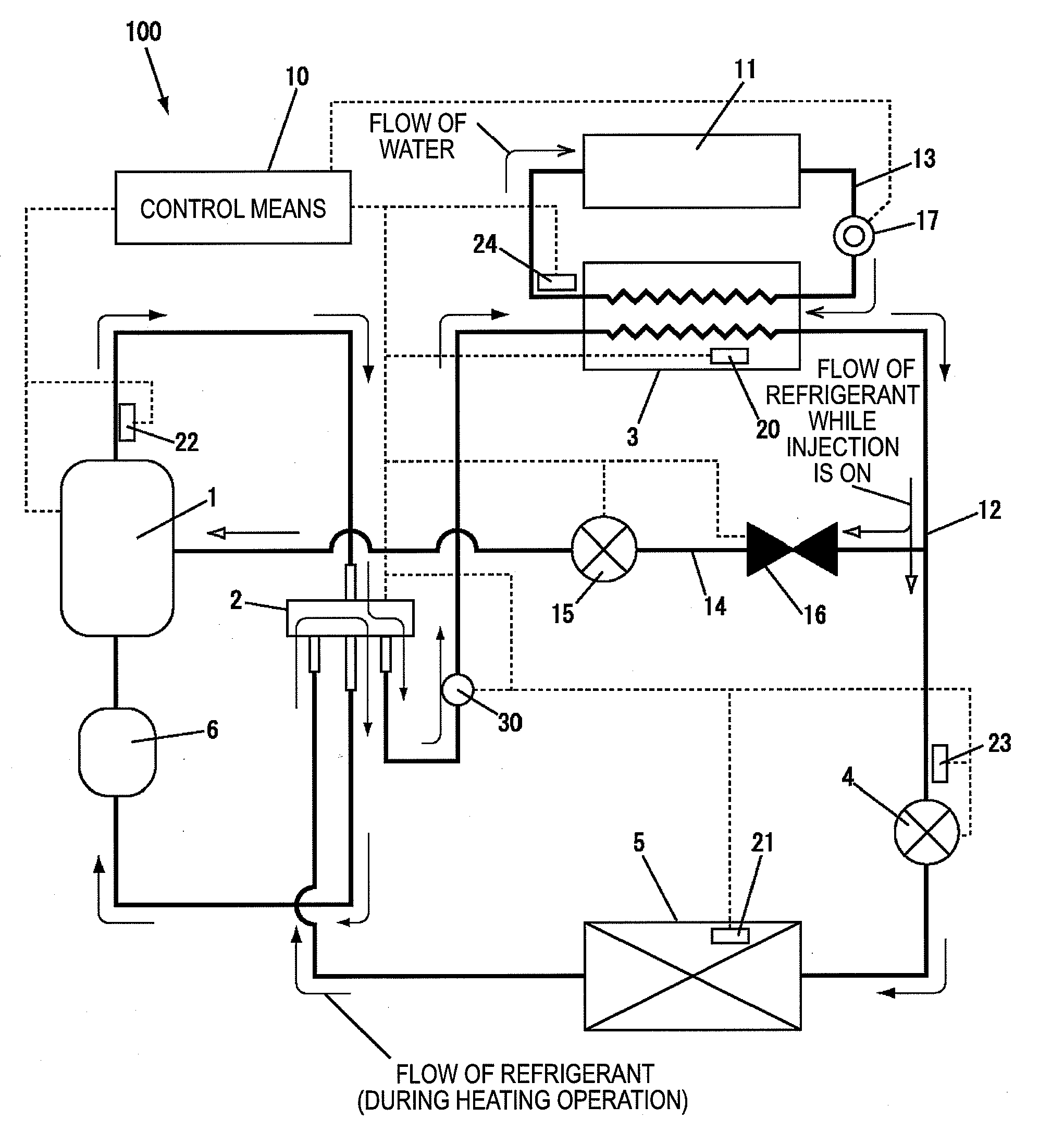
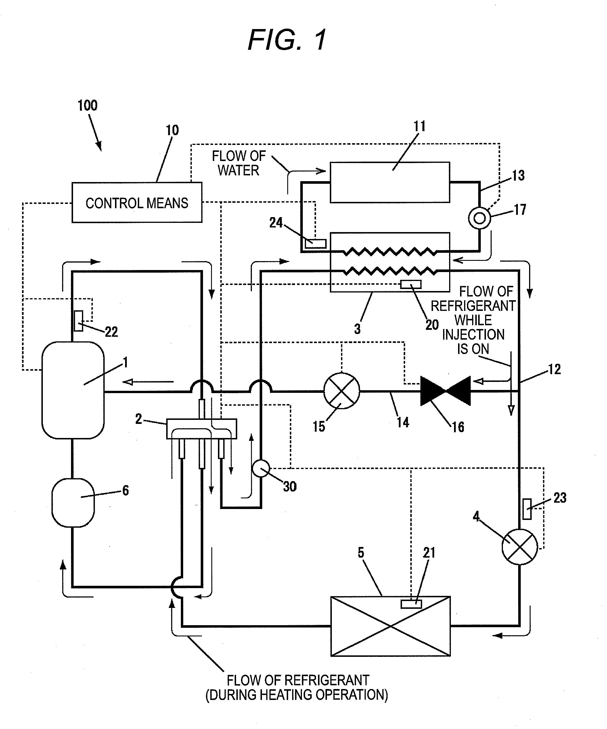
[0021]FIG. 1 shows structure of the heat pump apparatus according to the invention. The heat pump apparatus 100 includes a refrigerant circuit in which a compressor 1, a four way valve 2, an utilization-side heat exchanger 3 for conducting heat exchange between refrigerant and water, a first expansion valve 4, an outdoor heat exchanger 5, and an accumulator 6 are sequentially connected by means of a refrigerant pipe 12, and is so constructed that a direction of circulating the refrigerant is converted by switching the four way valve 2. Moreover, an inlet of the refrigerant of the compressor 1, which is not shown, is connected to the refrigerant pipe 12 at a point between the utilization-side heat exchanger 3 and the first expansion valve 4, by means of an injection pipe 14 having a second expansion valve 15 and a solenoid switching valve 16.

[0022]The utilization-side heat exchanger 3 is provided with a heat exchange temperature sensor 20 for detecting temperature of the refrigerant ...

exemplary embodiment 2

[0062]Now, a second exemplary embodiment of the heat pump apparatus according to the invention will be described. In this exemplary embodiment, the structure of the heat pump apparatus, the refrigerant circuit, operational principle of the injection ON / OFF, control of the supercooling degree when the injection is OFF, and effects of the correction of the objective SC value when the injection is ON are the same as in the first exemplary embodiment, and therefore, description of them will be omitted. The second exemplary embodiment is different from the first exemplary embodiment in that the memory part of the control means 10 has a table of corrected objective SC values (Tc) in which the objective SC values when the injection is ON are stored, and the supercooling degree is controlled by extracting the objective SC value from this corrected objective SC value (Tc) table.

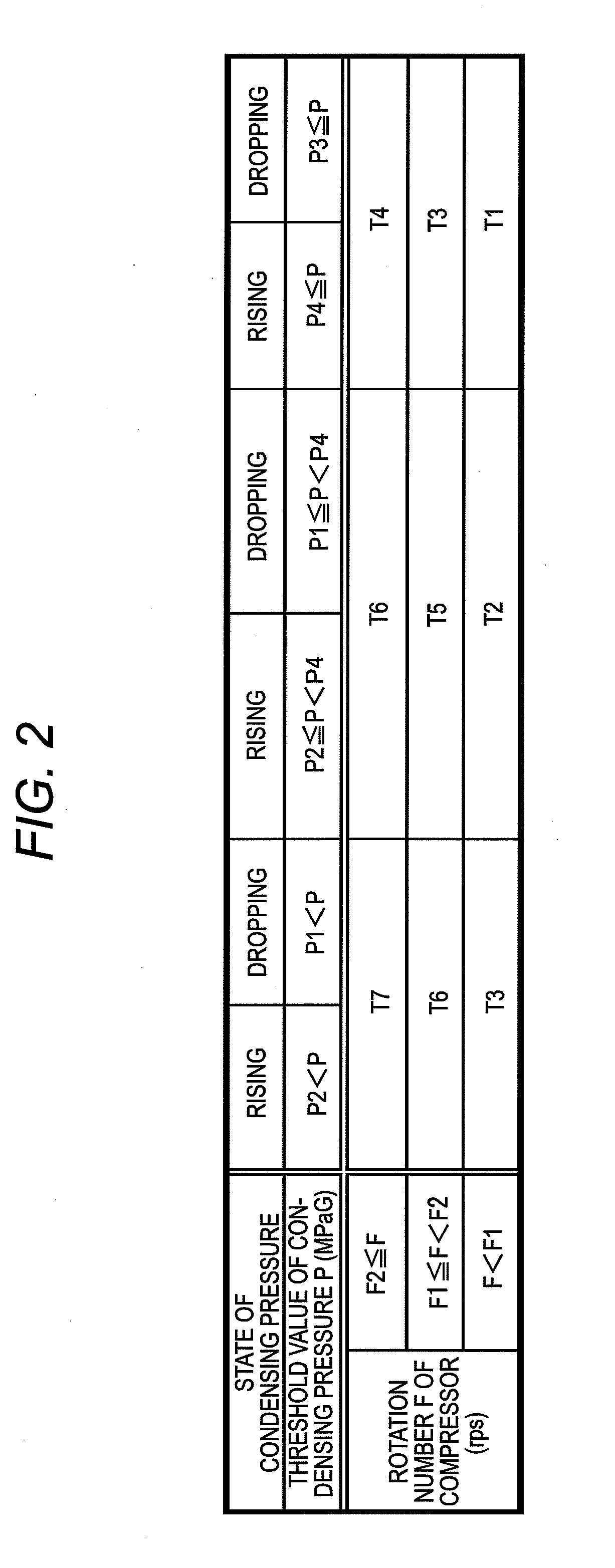
[0063]In addition to the objective SC (T) table in FIG. 2, the corrected objective SC value (Tc) table as shown in ...


PUM


Abstract

A heat pump apparatus includes: a refrigerant circuit which includes a compressor, an utilization-side heat exchanger, a first expansion valve, and an outdoor heat exchanger; an injection pipe which includes a solenoid switching valve and a second expansion valve; and an objective supercooling degree table which stores objective supercooling degrees according to condensing pressure in the refrigerant circuit and rotation number of the compressor. In the heat pump apparatus, liquid refrigerant is injected to the compressor by way of the injection pipe. The heat pump apparatus switches between a first case where the liquid refrigerant is injected to the compressor and a second case where the liquid refrigerant is not injected, and a value of the objective supercooling degree is changed between the first case and the second case to control the first expansion valve based on the value of the objective supercooling degree.

Description

[0001]This application claims priority from Japanese Patent Application No. 2009-225954, filed on Sep. 30, 2009, and Japanese Patent Application No. 2009-237875, filed on Oct. 15, 2009, the entire contents of which are hereby incorporated by reference.FIELD OF THE INVENTION[0002]The present invention relates to a heat pump apparatus such as a heat pump type floor heater, a water heater, etc., and more particularly, to the heat pump apparatus in which efficient operation control suitable for generating hot water is executed.DESCRIPTION OF RELATED ART[0003]Generally, an air conditioner is a typical apparatus as a heat pump apparatus. As the air conditioner which can exert high heating ability at high coefficient of performance (COP), even in case where an outdoor air temperature is low, there has been proposed an related-art air conditioner provided with a refrigerant circuit for injecting liquid refrigerant to a compressor (For example, see Japanese Patent No. 3080558).[0004]In the r...

Claims


Application Information

Patent Timeline
IPC IPC(8): F25B41/04F25B1/00F25B41/00
CPCF24D3/18Y02B30/12F25B2313/02741F25B2313/0314F25B2313/0315F25B2339/047F25B2400/13F25B2600/0253F25B2600/13F25B2600/19F25B2600/2509F25B2600/2513F25B2700/195F25B2700/21F25B2700/2106F25B2700/21152Y02B30/741Y02B30/745F25B31/008F25B13/00Y02B30/70
Inventor ITAGAKI, ATSUSHISUGIYAMA, TAKASHIFUJI, TOSHIYUKI
Owner FUJITSU GENERAL LTD
Learn More