
Strip edge shape control apparatus and method in strip casting process

a strip casting and control apparatus technology, applied in the direction of manufacturing tools, foundation moulding apparatus, melt-holding vessels, etc., can solve the problems of high roll force, deterioration of the quality of the side, and non-solidification of molten steel and strip breakdown, so as to prolong the life of the edge dam, suppress the generation of strip scraps, and improve the quality and productivity of the strip

Inactive Publication Date: 2011-03-31
POHANG IRON & STEEL CO LTD
View PDF1 Cites 2 Cited by
  • Summary
  • Abstract
  • Description
  • Claims
  • Application Information

AI Technical Summary

Benefits of technology

[0014]The present invention has been made in order to solve the above-described problems occurring in the prior art, and it is an object of the present invention to provide an apparatus and method for controlling the edge shape of a strip in a twin-roll strip casting process, which comprise observing with a camera a strip being produced in situ, transmitting the observation results to an operation room, analyzing the edge quality of the strip through image processing, and then increasing or decreasing the wear rate and upward shift rate of the edge dams depending on the quality of the strip, thus improving the edge quality of the strip and increasing the life span of the expensive edge dams.Technical Solution
[0023]The present invention provides the effect of improving the quality and productivity of a strip in a twin-roll strip casting process.
[0025]Namely, the present invention provides the effects of suppressing the generation of strip scraps and extending the life span of an edge dam, thus reducing production cost.

Problems solved by technology

For example, if the roll gap is excessively great or if the casting speed is excessively high, the solidification point will decrease below the temperature of the center line of roll nips, such that the roll force gradually decreases, thus causing the non-solidification of molten steel and strip breakdown.
In the contrary case, the solidification point will increase, leading to high roll force.
If molten steel flows into the gap, it will deteriorate the quality of the side of a cast strip, that is, the edge quality of the cast strip, thus reducing the value of the cast strip and abnormally wearing the ceramic material of the edge dam to make normal casting impossible.
Moreover, in many cases, a skull that almost inevitably occurs due to the temperature drop of molten steel and the surrounding devices during casting is incorporated between the sides of the rolls and the edge dams, and thus the seal plate of the edge dam is damaged.
For this reason, an edge fin occurs at the edge portion of a cast strip being produced, leading to deterioration in the quality of the cast strip.
However, the oscillation of the edge dams additionally wears the seal plate of the edge dams to form an unnecessarily worn portion between the seal plate of the edge dams and the end face of the rolls, and if molten steel penetrates into and is solidified in that portion, burrs will be formed on a cast strip being produced, thus making the edge shape of the strip poor.
However, much time is required for an operator to visually analyze the strip coming out of a casting machine, to return to an edge dam controller in an operation room and to analyze the analysis results.
Due to this time delay, molten steel and a skull are incorporated between the sides of the rolls and the edge dams, damaging the seal plate of the edge dams, so that the quality of the cast strip becomes poor and the life span of the expensive edge dams is shortened.

Method used


Image

  • Strip edge shape control apparatus and method in strip casting process
  • Strip edge shape control apparatus and method in strip casting process
  • Strip edge shape control apparatus and method in strip casting process

Examples


Embodiment Construction

[0030]Hereinafter, the present invention will be described in detail with reference to the accompanying drawings.

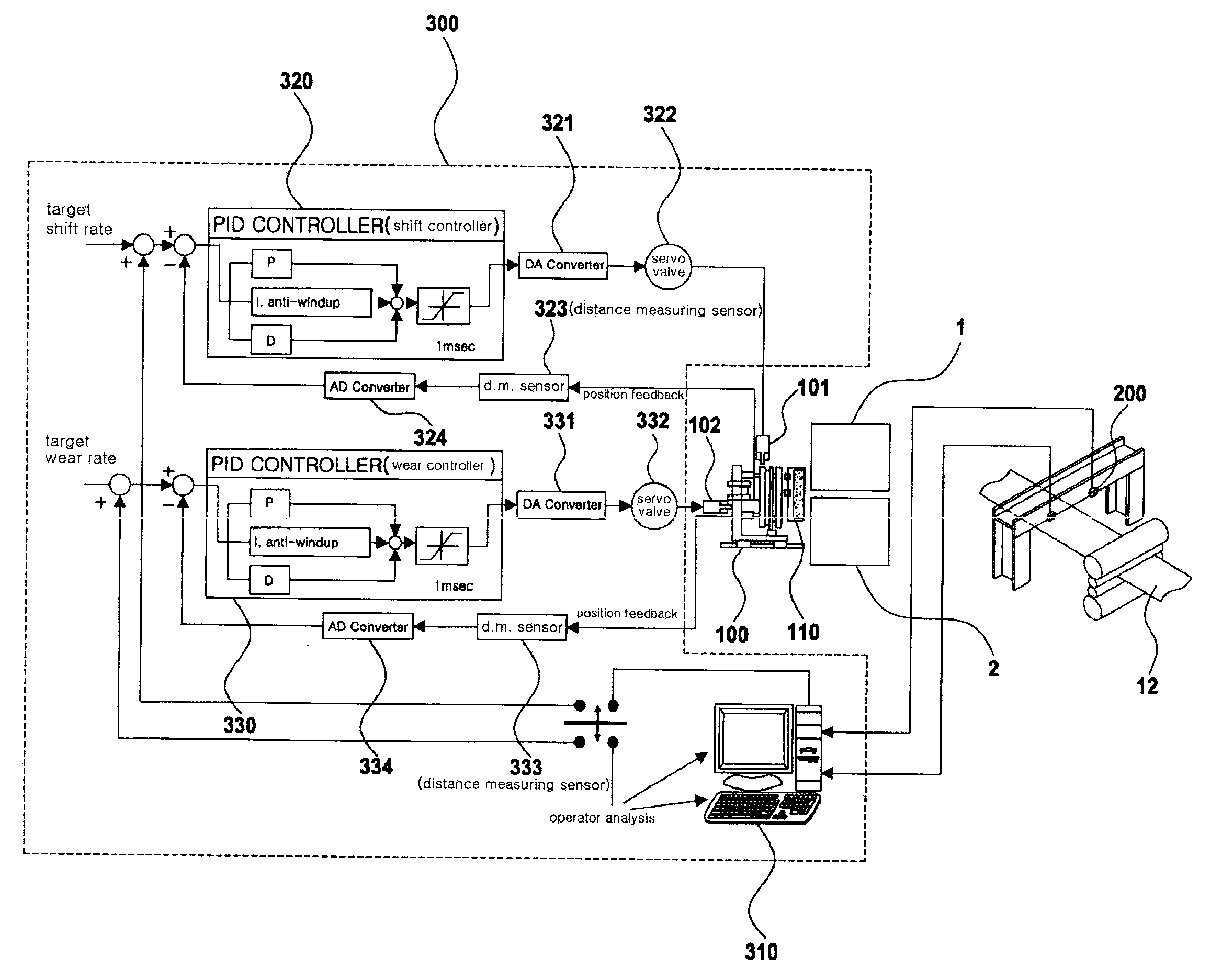
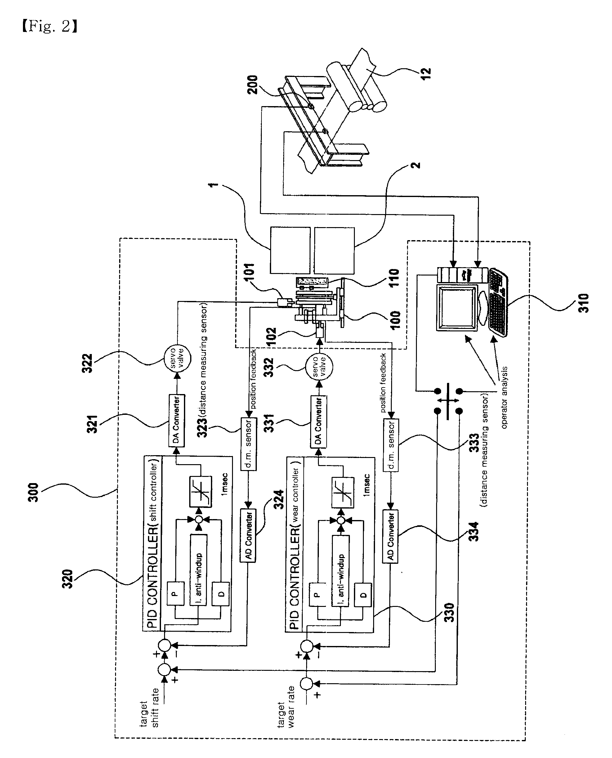
[0031]FIG. 2 is a block diagram showing the construction of an apparatus for controlling the edge shape of a strip in a twin-roll strip casting process (hereinafter referred to as “edge shape control apparatus”) according to an embodiment of the present invention, and FIG. 3 is a view showing the position of cylinders attached to an edge dam.

[0032]As shown in FIG. 2, the edge shape control apparatus comprises an edge dam driving unit 100 which is attached to both sides of casting rolls so as to control the pressing force of the edge dams against the casting rolls and the upward shift of the edge dams depending on the wear and upward shift rate of the edge dams; cameras 200 which are disposed at both sides of the edge dams at the outlet side of the casting rolls 12 through which a strip 12 is discharged, the cameras serving to photograph the edge portion of the strip; and ...


PUM

PropertyMeasurementUnit
thicknessaaaaaaaaaa
lengthaaaaaaaaaa
lengthaaaaaaaaaa

Abstract

Disclosed herein are an apparatus and method for controlling the edge shape of a strip in a twin-roll strip casting process, which improve the quality of the strip by using cameras to photograph the edge portions of the strip being cast by strip casting, analyzing the photographs, and then controlling edge dams according to the edge shape of the strip. The apparatus comprises: an edge dam driving unit which is attached to edge dams attached to both sides of casting rolls so as to control the pressing force of the edge dams against the casting rolls and the upward shift of the edge dams according to the wear and upward shift rate of the edge dams; cameras which are disposed at the strip outlet side of the casting rolls so as to photograph the edge portions of the strip; and a control unit which analyzes the edge shape of the strip from images photographed by the cameras and outputs a signal controlling the wear and upward shift of the edge dams.

Description

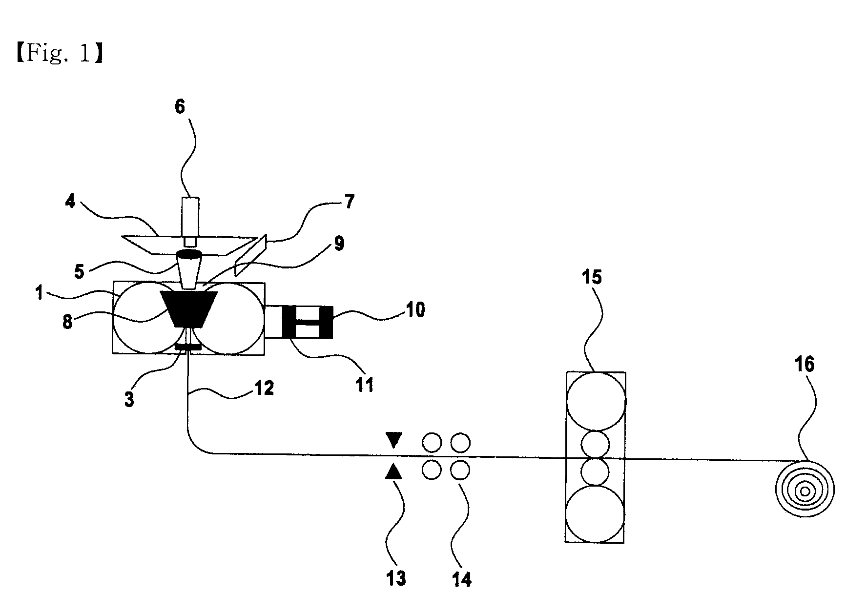
TECHNICAL FIELD[0001]The present invention relates to the control of the edge shape of a strip in strip casting, and more particularly to an apparatus and method for controlling the edge shape of a strip in a twin-roll strip casting process, which improve the quality of the strip by using cameras to photograph the edge portions of the strip being cast by strip casting, analyzing the photographs, and then controlling edge dams according to the edge shape of the strip.BACKGROUND ART[0002]FIG. 1 is a view showing the construction of a strip casting apparatus according to the prior art. As shown in FIG. 1, an important process for strip casting generally occurs in a sump between two rolls 1 and 2 that rotate in directions opposite to each other.[0003]When molten steel is supplied to the sump 9 through a submerged entry nozzle 5 from a tundish 4, the molten steel is solidified between a leader strip and the two rolls within 0.2 seconds and rolled. Herein, the molten steel, the leader str...

Claims


Application Information

Patent Timeline
Patent Type & Authority Applications(United States)
IPC IPC(8): B22D11/16B22D2/00
CPCB22D11/0622B22D11/16B22D11/066B22D11/185B22D41/50
Inventor KIM, YOON-HAKIMCHEONG, HAN-NAM
Owner POHANG IRON & STEEL CO LTD
Learn More