Welding contact tips for pulse applications

Active Publication Date: 2011-03-31
ILLINOIS TOOL WORKS INC
View PDF14 Cites 9 Cited by
  • Summary
  • Abstract
  • Description
  • Claims
  • Application Information

AI Technical Summary

Benefits of technology

[0012]The present invention provides a welding torch contact tip in which the welding current is split, varied, and spread along a front end length such that the contact tip generally has a lower maximum welding current as well as a lower decrease in welding current in relation to usage time (i.e., “arc-on” time), and therefore a lower deterioration rate. The present contact tip generally includes a contact tip body and a contact tip cap mounted on a front end of the body. The cap provides a portion of the contact area between the electrode wire and the contact tip during at least most of the useful lifespan of the contact tip.

Problems solved by technology

The high welding current and high current ramp rate transferring across the contact tip-electrode wire interface during pulse welding applications causes local melt or evaporation (e.g., arc erosion) on both the electrode wire and the contact tip.
Arc erosion during pulse welding applications causes substantial wear removal of the contact tip, and practical data indicates that contact tips deteriorate faster in pulse welding applications in comparison to constant voltage applications.
As the contact tip deteriorates with use, the energy transfer efficiency across the interface of the contact tip and electrode wire decreases, resulting in a drop in welding current.
When the current drops to a certain value, the energy consumption at the welding arc is insufficient to maintain proper melting of the electrode wire and a proper welding pool, resulting in an unstable arc and welding defects such as “skinny beads,”“broken beads,” and insufficient “leg length,”“wetting,” or “penetration.” This is the most common failure mechanism for contact tips used in modern pulse or controlled short circuit welding processes, and requires replacement of the worn contact tip with a new contact tip to maintain production quality.
Otherwise, welding defects such as “blow through” or “undercut” may occur.
These requirements narrow down the acceptable window (upper max and lower min) of welding current that a contact tip must provide, also shortening the useful life of the contact tip.
While much effort has been put into improving the materials and design of welding torch contact tips to mitigate contact tip deterioration, almost none of this effort has focused on the deterioration mechanisms of the contact tip as a way to improve contact tip life.
However, in pulse welding applications, the high pulse welding current is enlarged by this distribution and causes significant damage to the front end of the contact tip.

Method used


Image

  • Welding contact tips for pulse applications
  • Welding contact tips for pulse applications
  • Welding contact tips for pulse applications

Examples


Embodiment Construction

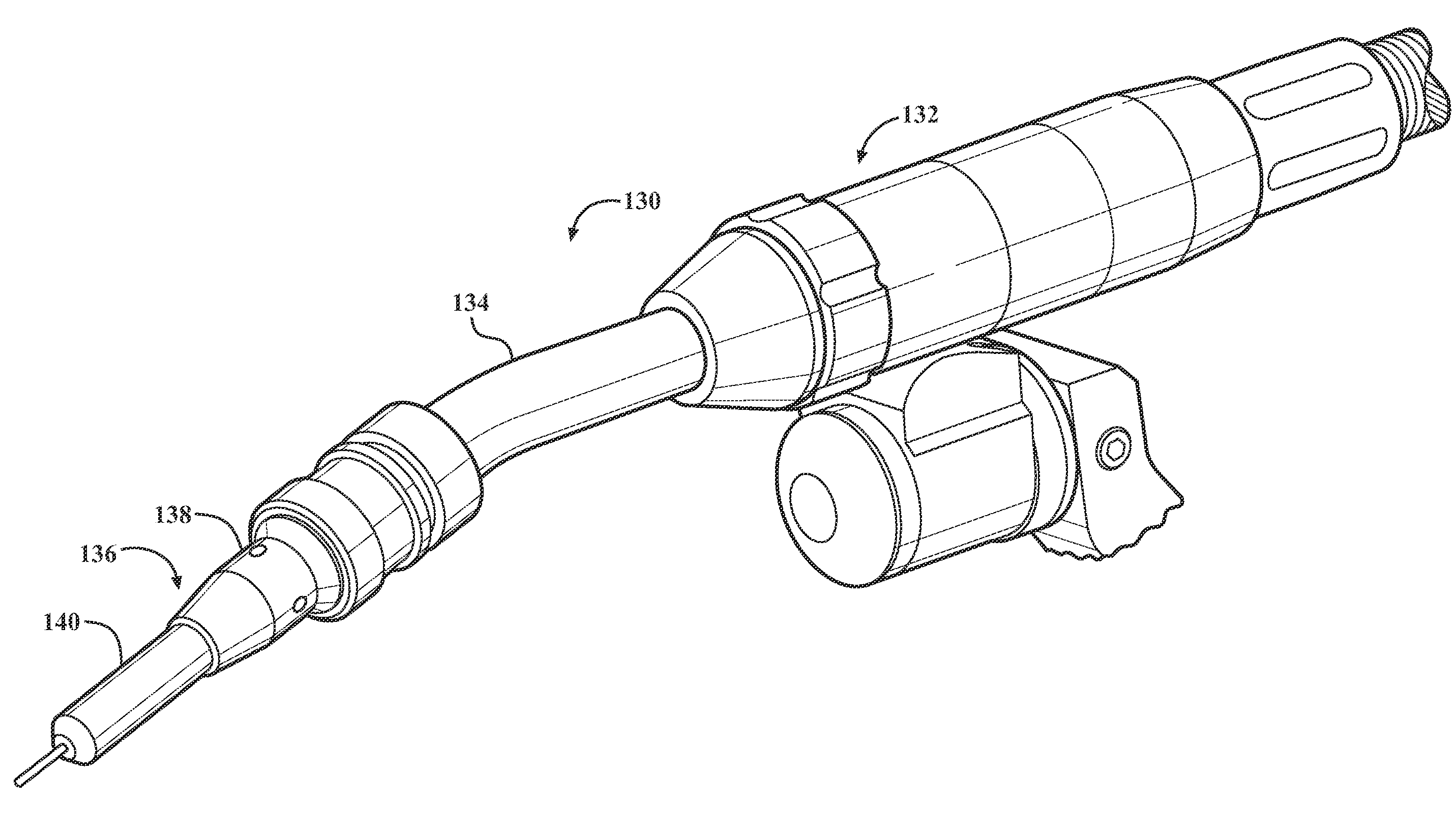
[0040]Referring now to the drawings in detail, numeral 130 generally indicates a welding torch such as a gas metal arc welding (GMAW) torch or a similar welding torch. As shown in FIG. 4, the welding torch 130 broadly includes a torch body 132, a neck such as a gooseneck 134 extending from a forward end of the torch body, and a contact tip assembly 136 at a distal end of the gooseneck. The contact tip assembly 136 generally includes a retaining head 138 and contact tip 140, which is discussed in greater detail below. During use of the welding torch 130, the contact tip assembly 136 may be covered and protected by a nozzle. A cable (not shown) is connected to a rear end of the torch body 132. The cable supplies electrical current, shielding gas, and a consumable electrode wire (e.g., a metal welding wire) to the torch body 132. The electrode wire travels through the torch body 132 to the gooseneck 134 and ultimately exit through an orifice in the contact tip assembly 136.

[0041]The we...


PUM

PropertyMeasurementUnit
Temperatureaaaaaaaaaa
Lengthaaaaaaaaaa
Lengthaaaaaaaaaa

Abstract

A contact tip for a welding torch includes a body having a front discharge end, an opposite rear feed end, and a bore extending through the body. A cap is mounted on the body at the front end. The cap has an aperture generally aligned with the bore. The cap is composed of a material having an electrical conductivity between 1.74×10⁷ and 4.35×10⁷ Siemens per meter at 20° C. The body is composed of a material selected from the group consisting of copper and a copper alloy. The body has an electrical conductivity that is higher than the electrical conductivity of the cap. A portion of the bore at the front end of the body and at least a portion of the aperture in the cap define a contact area for a consumable electrode wire.

Description

CROSS REFERENCE TO RELATED APPLICATION[0001]This application claims the priority of U.S. Provisional Application No. 61 / 245,749 filed Sep. 25, 2009.TECHNICAL FIELD[0002]This invention relates to contact tips for a GMAW (gas metal arc welding), MIG (metal inert gas), MAG (metal active gas), SAW (submerged arc welding), or FCAW (flux cored arc welding) welding torch, and more particularly to a contact tip having increased durability, especially in pulse welding applications.BACKGROUND OF THE INVENTION[0003]A conventional welding torch generally includes a cable assembly connected to a torch body, a gooseneck extending from the body, and a torch head at a distal end of the gooseneck. The torch head typically includes a retaining head and / or diffuser, a contact tip, and a nozzle. Welding wire (consumable electrode) and shielding gas are fed through the cable assembly and gooseneck to the torch head, where the welding wire and shielding gas are fed out of the contact tip.[0004]Common met...

Claims


Application Information

Patent Timeline
IPC IPC(8): B23K9/12
CPCB23K9/123
Inventor MA, TIEJUN
Owner ILLINOIS TOOL WORKS INC
Why Eureka
Try Eureka