Particle beam cooling device

a cooling device and particle beam technology, applied in the direction of accelerators, electric discharge tubes, electrical apparatus, etc., can solve the problems of limiting the ability to change, difficult to manipulate, and many seconds to achieve significant reduction, so as to reduce the emittance of charged particle beams, increase the acceptance of particles, and high intensity

Inactive Publication Date: 2011-03-31
MUONS
View PDF3 Cites 0 Cited by
  • Summary
  • Abstract
  • Description
  • Claims
  • Application Information

AI Technical Summary

Benefits of technology

[0015]In accordance with the present invention, there is provided a device railed a particle refrigerator or particle beam cooling device that will reduce the emittance of a charged particle beam. The beam is matched to a frictional cooling channel, increasing its acceptance by perhaps a thousandfold, thus making it practical to generate high intensity and high brightness beams. An aspect of this approach, thus, is that the emittance of the beam is reduced, while that of the electrons inside an absorber is increased.
[0016]The particle refrigerator device is particularly well-suited for beams of particles created by the interaction or decay of other particles, such as anti-protons, pions, ions, and muons, which are inherently created with very large emittances. An aspect of the device is that it may be provided in embodiments that are compact and inexpensive in contrast with other systems for the emittance reduction of such beams.
[0017]The particle beam cooling device has a container defining a chamber and an external beam pipe in fluid communication with the chamber. The beam pipe is configured with respect to a first direction so as to receive beam particles and to admit them into the chamber as they travel along an input or first direction. There is a frictional cooling channel also in fluid communication with the chamber and configured along an output or second direction. The frictional cooling channel has an acceptance due to an absorber positioned within the chamber for reducing the average energy of the beam particles of the input beam.
[0022]The chamber and external beam pipe are configured to contain a vacuum which the absorber within has a plurality of planar film conductors positioned within the chamber. The planes are substantially orthogonal to the first direction for reducing the energy of the particles of the input beam incident on the conductors, where the conductors have an average thickness in the first direction. The voltage distribution subsystem is in conductive communication with the plurality of planar film conductors where the plurality of planar film conductors, the average thickness, the power supply, the voltage distribution subsystem, and the transverse focusing subsystem are configured so as (i) to reduce the average beam particle energy a desired amount to a second average particle energy, (ii) to create a particle turn-around within the chamber, and (iii) to redirect the input beam in a first direction to a second direction as an output beam incident on the frictional cooling channel. Again the second average energy of the output beam particles matches the acceptance of the frictional cooling channel.

Problems solved by technology

This makes them very difficult to manipulate, so devices and techniques to reduce their emittance are highly desirable, especially to generate beams with high intensity and high brightness.
The emittance of a beam is the volume of six-dimensional phase space that its ensemble of particles occupies, and Liouville's theorem limits the ability to change it.
Unfortunately it requires many seconds to achieve a significant reduction, and is thus unsuitable for beams of unstable particles (such as pions or muons, which may have an at-rest lifetime of about 26 ns or 2.2 μs respectively).
It also requires large and expensive apparatus.
This, too, requires seconds to achieve a significant reduction, and is thus unsuitable for beams of unstable particles (such as pions or muons).
It also requires large and expensive apparatus.
This can happen quickly enough for beams of unstable particles, but conventional approaches in ionization cooling require large and expensive apparatus.
Unfortunately, the acceptance (i.e., the maximum value of beam emittance able to enter) of such a channel is quite small, as the panicles must have very low speed to enter it, so to date nobody has been able to use this for beams with high intensity or high brightness.

Method used


Image

  • Particle beam cooling device
  • Particle beam cooling device
  • Particle beam cooling device

Examples


Embodiment Construction

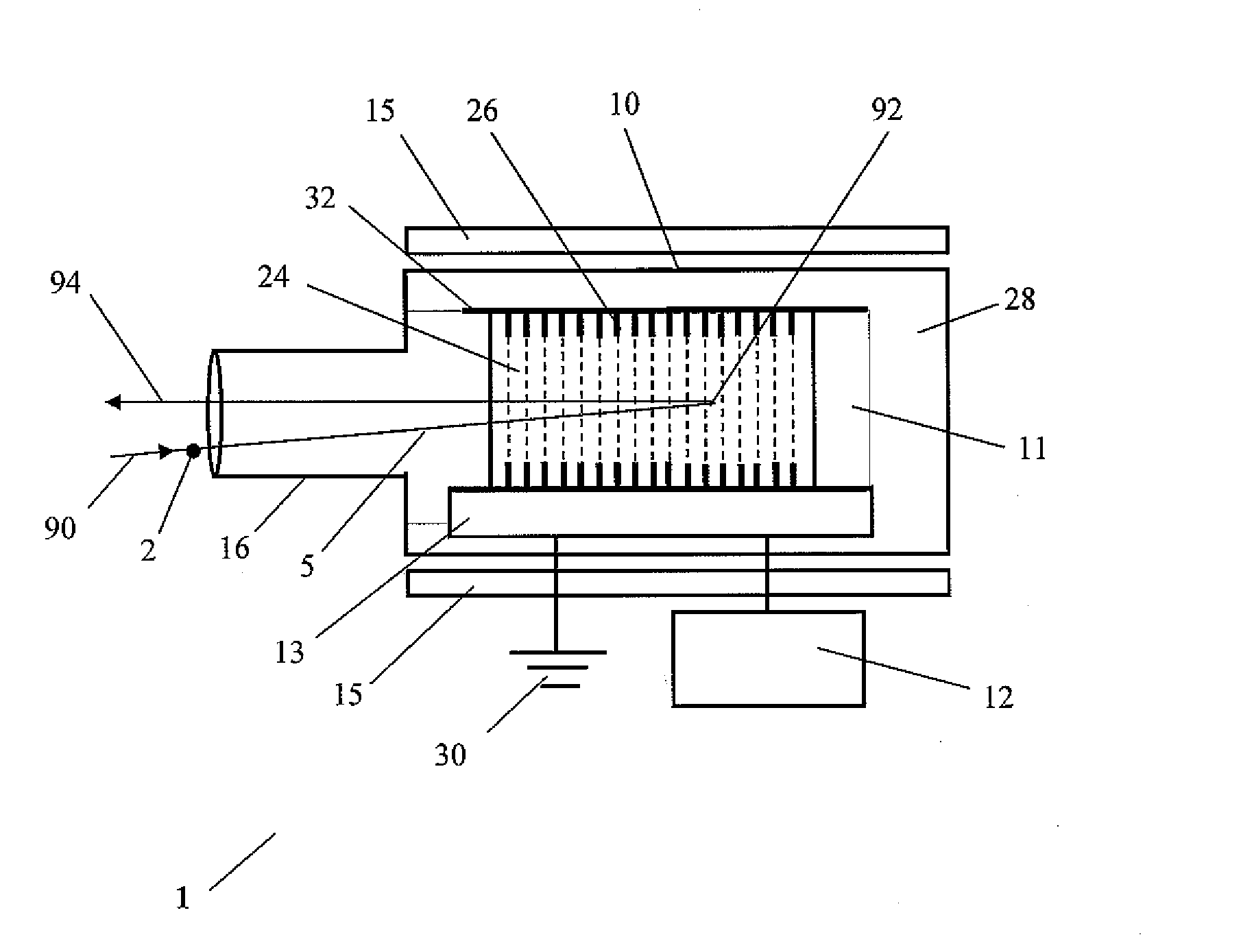
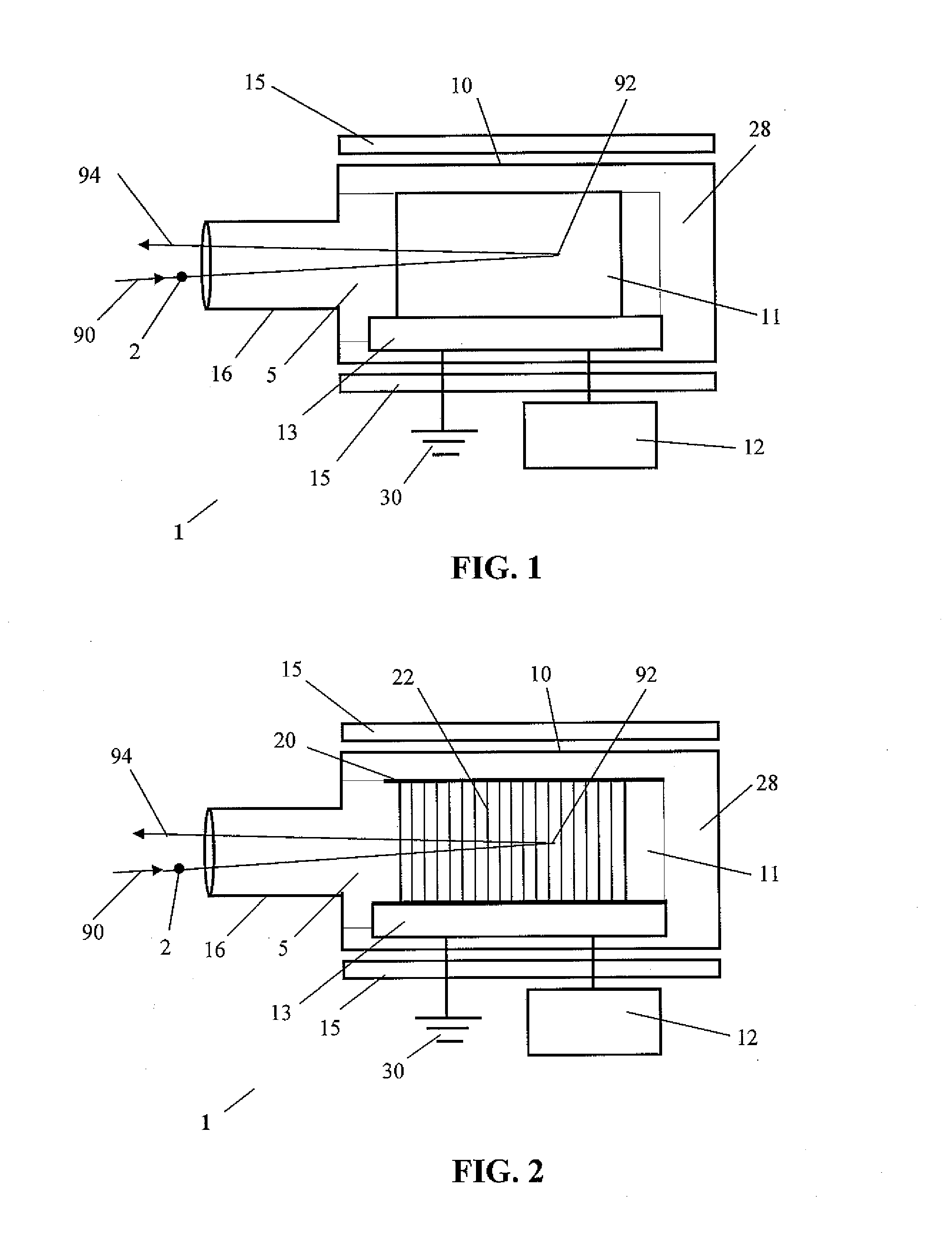
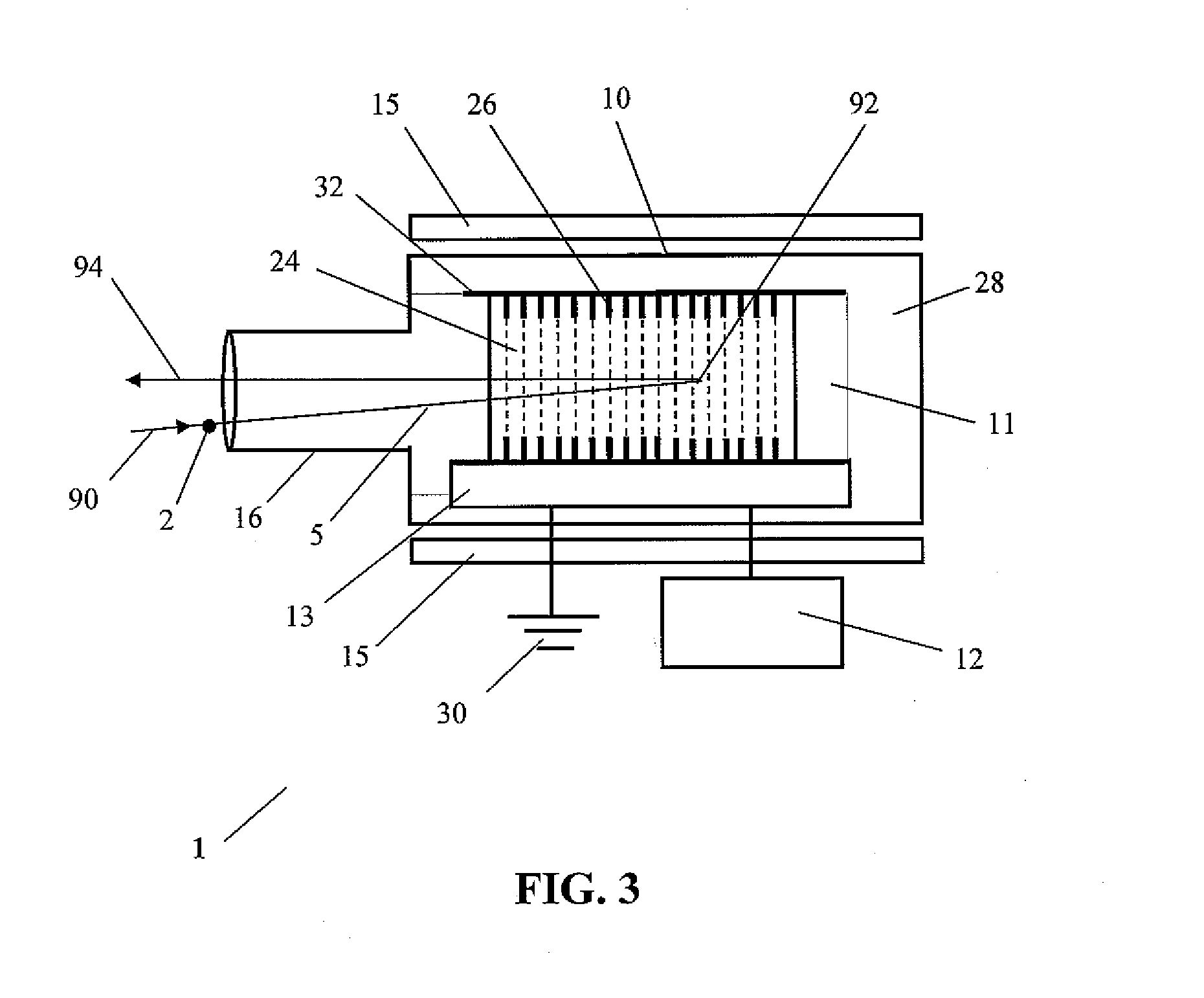
[0033]This device works by matching an incoming beam to a frictional cooling channel, and increasing the acceptance of that channel by perhaps a thousandfold, making it practical to produce beams of high intensity and brightness. A problem is that the acceptance of the frictional cooling channel is generally quite small, with an energy width of just a few kilo-electron-volts. An aspect of this device is to redirect the input beam particles inside the device to an outgoing or output beam (i.e., a particle turn-around), and then to direct the turned-around particles into the acceptance of an outgoing or output frictional cooling channel. By injecting the beam substantially backwards into the device (i.e., with respect to the ultimate, outgoing or output beamline), and having turned it around to exit the device through a frictional cooling channel, the effective energy acceptance of the device is approximately that of the high voltage used, which is on the order of several Mega-Volts i...


PUM


Abstract

This discloses a device called a particle refrigerator that will reduce the emittance of a charged particle beam. The particle refrigerator device is particularly well-suited for beams of particles created by interactions or decays of other particles, such as anti-protons, pions, ions, and muons, which are inherently created with very large emittances. It is a compact and inexpensive device compared to other systems for the emittance reduction of such beams. This device works by injecting beam particles backwards into the device, using the particle turn-around to match an incoming beam into a frictional cooling channel; this increases the acceptance of that channel by perhaps a thousandfold, making it practical to produce beams of high intensity and brightness. The frictional cooling is very effective, and simulations of its operation and performance give emittance reduction factors exceeding 30,000, with transmissions as high as 70%.

Description

CROSS-REFERENCE TO RELATED APPLICATION[0001]The present application claims the benefit of U.S. Provisional Patent Application No. 61 / 247,181, filed Sep. 30, 2009, the entire disclosure of which is hereby incorporated by reference.STATEMENT REGARDING GOVERNMENT SUPPORT[0002]None.FIELD OF THE INVENTION[0003]This application relates to charged particle beams in general and, more particularly, to particle beam cooling device, including preparing and producing low energy, high brightness beams of particles produced by interactions or decay of other particles.BACKGROUND OF THE INVENTION[0004]Charged particle beams generated via interactions or decays are created with very large emittances. This makes them very difficult to manipulate, so devices and techniques to reduce their emittance are highly desirable, especially to generate beams with high intensity and high brightness. The emittance of a beam is the volume of six-dimensional phase space that its ensemble of particles occupies, and ...

Claims


Application Information

Patent Timeline
Patent Type & Authority Applications(United States)
IPC IPC(8): H01J23/08H05H7/00
CPCH05H7/12
Inventor ROBERTS, THOMAS J.
Owner MUONS
Why Eureka
Try Eureka