Eureka AIR delivers breakthrough ideas for toughest innovation challenges, trusted by R&D personnel around the world.

System, Method and Computer Program for Remotely Testing System Components Over A Network

Active Publication Date: 2011-03-31
EMAMI MOHAMMED REZA +1
View PDF6 Cites 18 Cited by
  • Summary
  • Abstract
  • Description
  • Claims
  • Application Information

AI Technical Summary

Benefits of technology

[0013]The present invention provides a test platform for enabling the testing of one or more system components, the test platform comprising: (a) one or more test fixtures for mounting one or more system components; (b) a load emulator; (c) a coupling for lin

Problems solved by technology

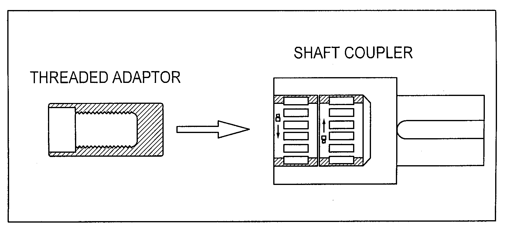
There are also issues with coupling an emulation system to a motor under test.
However, multi jawed couplings do not have a means for ensuring concentricity of the two shafts.
In other words, there is no means to correct parallel or angular misalignment.
These couplings are also severely limited in size; they cannot accommodate a shaft bore greater than ¼ inch.
In addition, positive contact clutches do not have a means of orienting the two hubs to facilitate safe engagement.
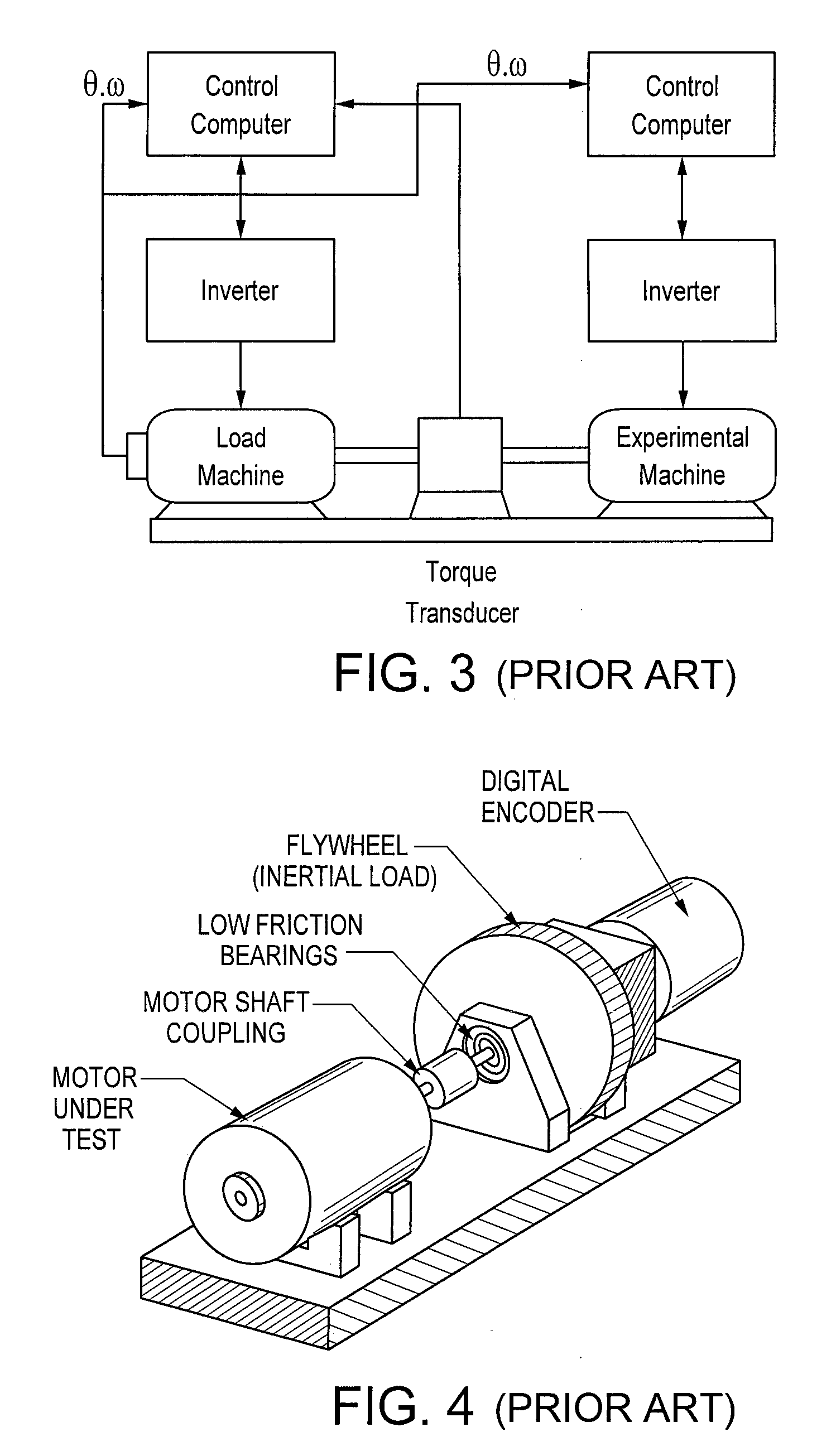
Dynamic load test systems are found mostly in academic literature and not in practical applications.
Due to their physics, dynamometers are heavy and bulky and cannot emulate fast dynamics.
Thus, they are usually used for large-size motors and in situations where the high costs of their acquisition, installation, and maintenance can be afforded.
However, because each motor has to be tested as it comes off the production line at production speed, the Digitorque system requires an automated means of coupling test motors coming off the production line to the test fixture.
However, while these solutions do allow for automated coupling, they are specific for the motor being tested.

Method used


Image

  • System, Method and Computer Program for Remotely Testing System Components Over A Network
  • System, Method and Computer Program for Remotely Testing System Components Over A Network
  • System, Method and Computer Program for Remotely Testing System Components Over A Network

Examples


Embodiment Construction

[0024]The present invention provides a test platform for enabling the testing of one or more system components. The test platform enables a load emulator to apply a load to the one or more system components. A coupling is provided for linking the load emulator to a selected system component to enable the load to be applied. A positioning system is operable to selectively position the coupling so as to link the load emulator to the selected system component.

[0025]For example, the system components may be one or more motors and the test platform may be a motor test platform. In this particular implementation, the motor test platform may also be provided with a tapered jawed assembly for eliminating torsional misalignment between the load emulator and the selected motor (to be tested) and enabling the coupling of any of the motors with no backlash. Other potential system components that can be tested in accordance with the present invention include, for example, motor drive systems, tr...


PUM


Abstract

The invention is a turn-key, modular platform, including software and hardware, for testing physical system components such as motors remotely over the Internet. The system allows remote customers to test multiple physical system components under the specific loading conditions of the real-world application. This will provide more detailed and accurate information than what is usually given in the data sheets for system component performance, enabling the user to make a more-reliable decision. With respect to motors, the hardware consists of a torque motor that moves autonomously in xy plane to couple to the individual test motors, through a unique coupling mechanism, and emulate various load profiles on them. Test motors are mounted onto modular fixtures that allow for one-time manual positioning in xyz space. The software, consisting of server and target applications, creates user accounts and profiles, controls user access by means of a scheduler, and enables each user to connect to the hardware via Internet and run a customized experiment.

Description

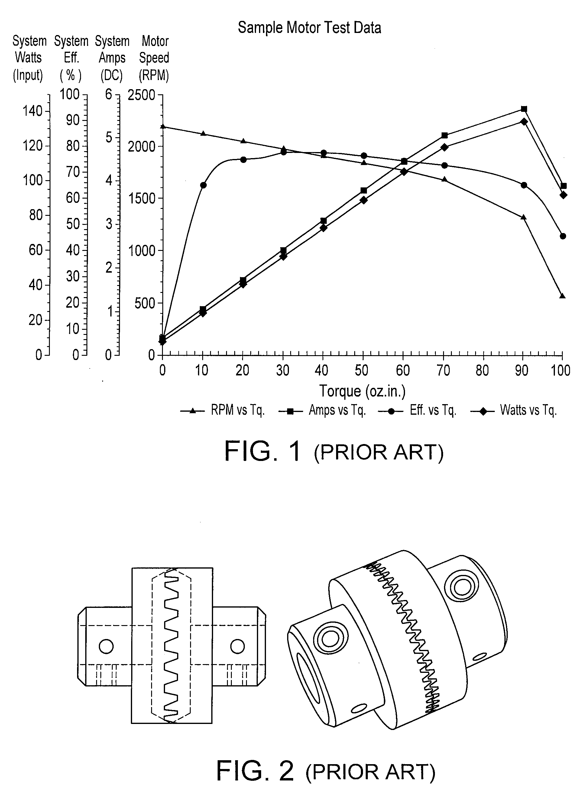
FIELD OF THE INVENTION[0001]The present invention relates to the field of testing, evaluation and selection of system components. The present invention more specifically relates to remotely testing mechanical system components such as motors over a network.BACKGROUND OF THE INVENTION[0002]A motor's torque / speed characteristics can be the most important factors when selecting a motor for a specific application. In both open-loop and closed-loop (servo) applications, the loading condition on a motor has critical effects on its dynamic response, efficiency, and power consumption, and the effect varies widely at different speeds. FIG. 1 shows an example of a torque-speed curve that is available for a typical brushless DC motor (24V, 50 oz-in NT Dynamo™ model, Hurst Manufacturing™). Information is also provided on current, efficiency and power output vs. torque.[0003]The existing motor performance charts in the datasheets that manufacturers provide to potential customers are based on ben...

Claims


Application Information

Patent Timeline
IPC IPC(8): G06F19/00G01M99/00
CPCH04L67/12G01M13/021H04L67/38H04L67/131
Inventor EMAMI, MOHAMMAD REZATEDESCO, MICHAEL-ANTHONY
Owner EMAMI MOHAMMED REZA
Why Eureka
Eureka Blog
Learn More