Internal Combustion Engine Having A Motor Brake Assembly

a technology of internal combustion engine and motor brake assembly, which is applied in the direction of valve arrangement, machine/engine, output power, etc., can solve the problems of time-consuming, costly and error-prone regular manual adjustment, and achieve the effect of safe and reliable operation and least possible expenditure on assembly and servicing

Active Publication Date: 2011-04-07
MAN NUTZFAHRZEUGE AG
View PDF12 Cites 31 Cited by
  • Summary
  • Abstract
  • Description
  • Claims
  • Application Information

AI Technical Summary

Benefits of technology

[0005]It is an object of the invention to provide an internal combustion engine of the type mentioned a...

Problems solved by technology

A time-consuming, costly and error-p...

Method used


Image

  • Internal Combustion Engine Having A Motor Brake Assembly
  • Internal Combustion Engine Having A Motor Brake Assembly
  • Internal Combustion Engine Having A Motor Brake Assembly

Examples


Embodiment Construction

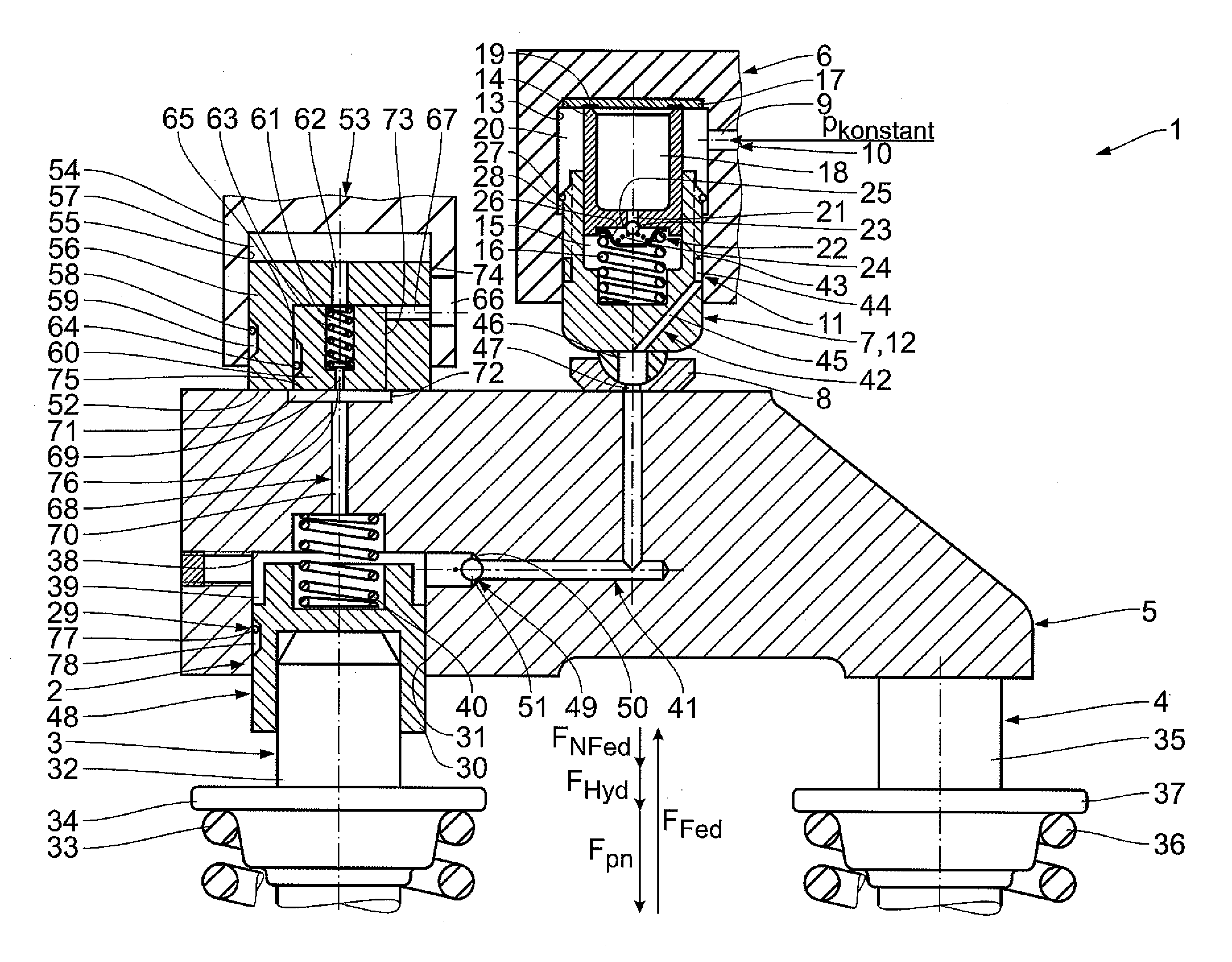
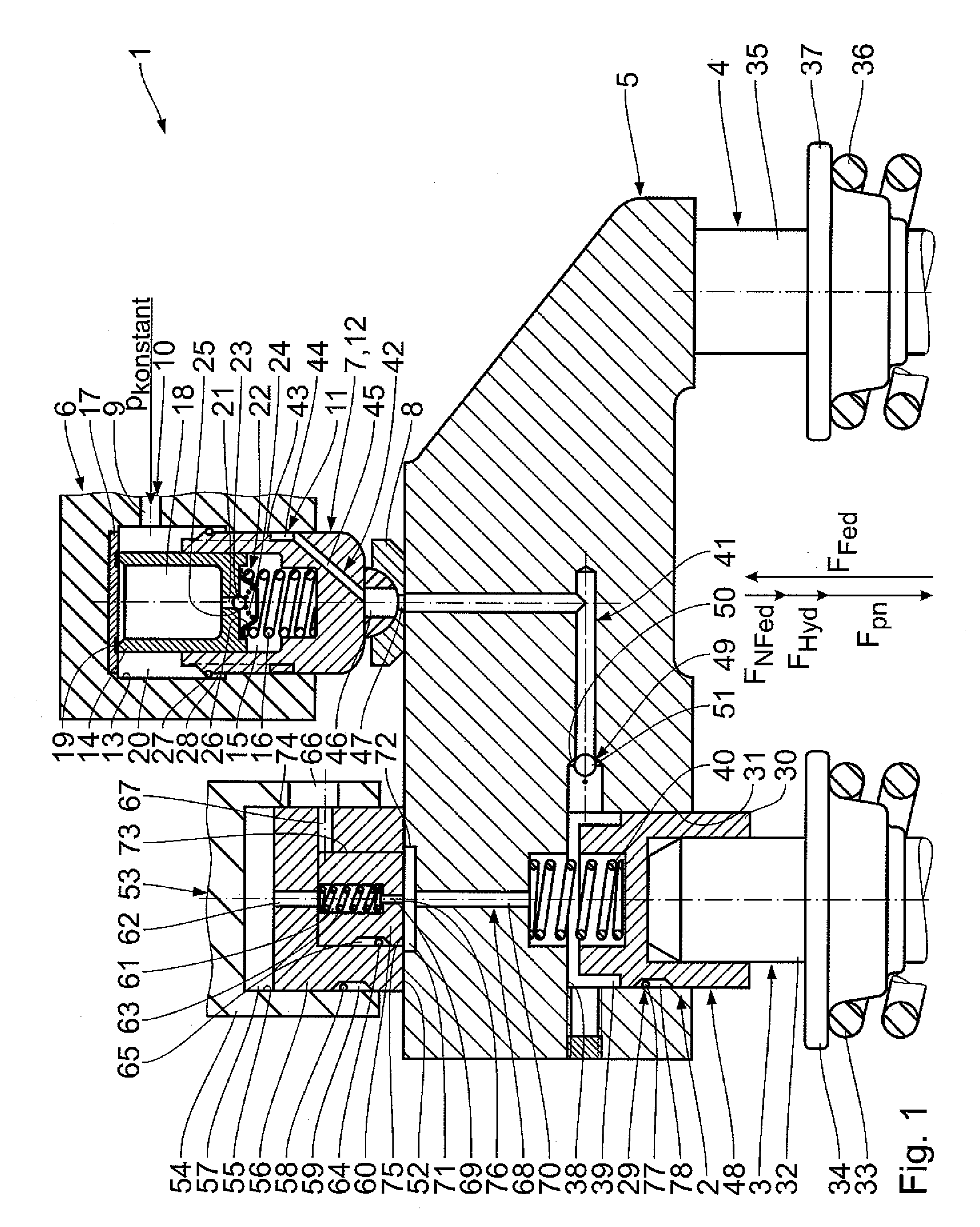
[0022]A first embodiment of the invention will be described in the following with reference to FIG. 1. An internal combustion engine 1 with an engine braking device 2 has a plurality of cylinders, not shown in FIG. 1, which define a combustion chamber. Air or an air-fuel mixture can be supplied to each of these combustion chambers by at least one inlet valve. Further, two exhaust valves 3 and 4, through which exhaust gas can be carried off in an exhaust gas duct, are associated with each combustion chamber. The exhaust valves 3 and 4 can be mechanically controlled and actuated by a common valve bridge 5. The valve bridge 5 is part of a connection mechanism that connects the exhaust valves 3 and 4 to a camshaft, not shown in FIG. 1, of the internal combustion engine 1. The connection mechanism comprises a pivotably mounted rocker arm 6 that acts on the valve bridge 5 via a contact stud 7. To this end, the contact stud 7 is provided at its free end with a support cup 8 which is articu...


PUM


Abstract

An internal combustion engine includes an exhaust valve for removing exhaust gas from a combustion chamber and an engine braking device with a hydraulic valve control unit by which the exhaust valve is held in an intermediate open position when the engine braking device is actuated. The internal combustion engine includes a hydraulic valve lash compensation mechanism for the exhaust valve and a control channel formed between the hydraulic valve control unit and an oil feed channel for feeding oil to the hydraulic valve control unit which can be closed by a closure element to compensate for valve lash of the exhaust valve. A counter-holder is constructed as a piston-cylinder unit that forms a variable stop for a valve bridge cooperating with the valve lash compensation mechanism.

Description

BACKGROUND OF THE INVENTION[0001]1. Field of the Invention[0002]The invention is directed to an internal combustion engine with an engine breaking device that is configured to maintain an exhaust valve in an intermediate position.[0003]2. Description of the Related Art[0004]An internal combustion engine of the type mentioned above is described in EP 1 526 257 A2. The engine braking device in this internal combustion engine is a combination of an engine exhaust brake and a compression release brake, also known as EVB (Exhaust Valve Brake). The hydraulic valve control unit is installed on one side in a valve bridge which actuates two exhaust valves simultaneously. The supply of oil to the valve control unit is carried out by the existing oil circuit in the internal combustion engine. Separate adjustment screws are provided for compensating valve lash in the exhaust valves and are used to adjust the valve lash when assembling the engine or afterwards at regular servicing intervals. Thi...

Claims


Application Information

Patent Timeline
IPC IPC(8): F02D13/04
CPCF01L1/24F01L13/06F01L1/26
Inventor DILLY, HANS-WERNER
Owner MAN NUTZFAHRZEUGE AG
Why Eureka
Try Eureka