Helical airfoil wind turbines

a technology of wind turbines and airframes, which is applied in the direction of wind motors with parallel air flow, wind motors with perpendicular air flow, liquid fuel engine components, etc., can solve problems such as not reducing efficiency, and achieve the effects of reducing negative drag, increasing efficiency, and reducing the weight of the turbin

Inactive Publication Date: 2011-04-07
SULLIVAN JOHN T
View PDF64 Cites 67 Cited by
  • Summary
  • Abstract
  • Description
  • Claims
  • Application Information

AI Technical Summary

Benefits of technology

[0009]It is a further object of this invention to provide a wind turbine comprised of airfoil blades made from a flexible material such that the blades bend towards the center of the turbine upon their return into the wind. This effectively reduces negative drag to further increase efficiency.
[0010]It is a further object of this invention to provide for airfoils in which the twisted blades contain cut-outs, or hollow sections in blades. These hollow sections provide for a decreased weight of the turbine while not reducing its efficiency.
[0011]It is a further object of this invention to provide a wind turbine that could be assembled from portable unit pieces to the desired length. It is a further object of this invention to provide a wind turbine that is lightweight and portable and requires minimum external support.
[0012]It is a further object of this invention to provide a wind turbine constructed from inflatable airfoils. It

Problems solved by technology

These hollow sections provide for a decreased weigh

Method used


Image

  • Helical airfoil wind turbines
  • Helical airfoil wind turbines
  • Helical airfoil wind turbines

Examples


Embodiment Construction

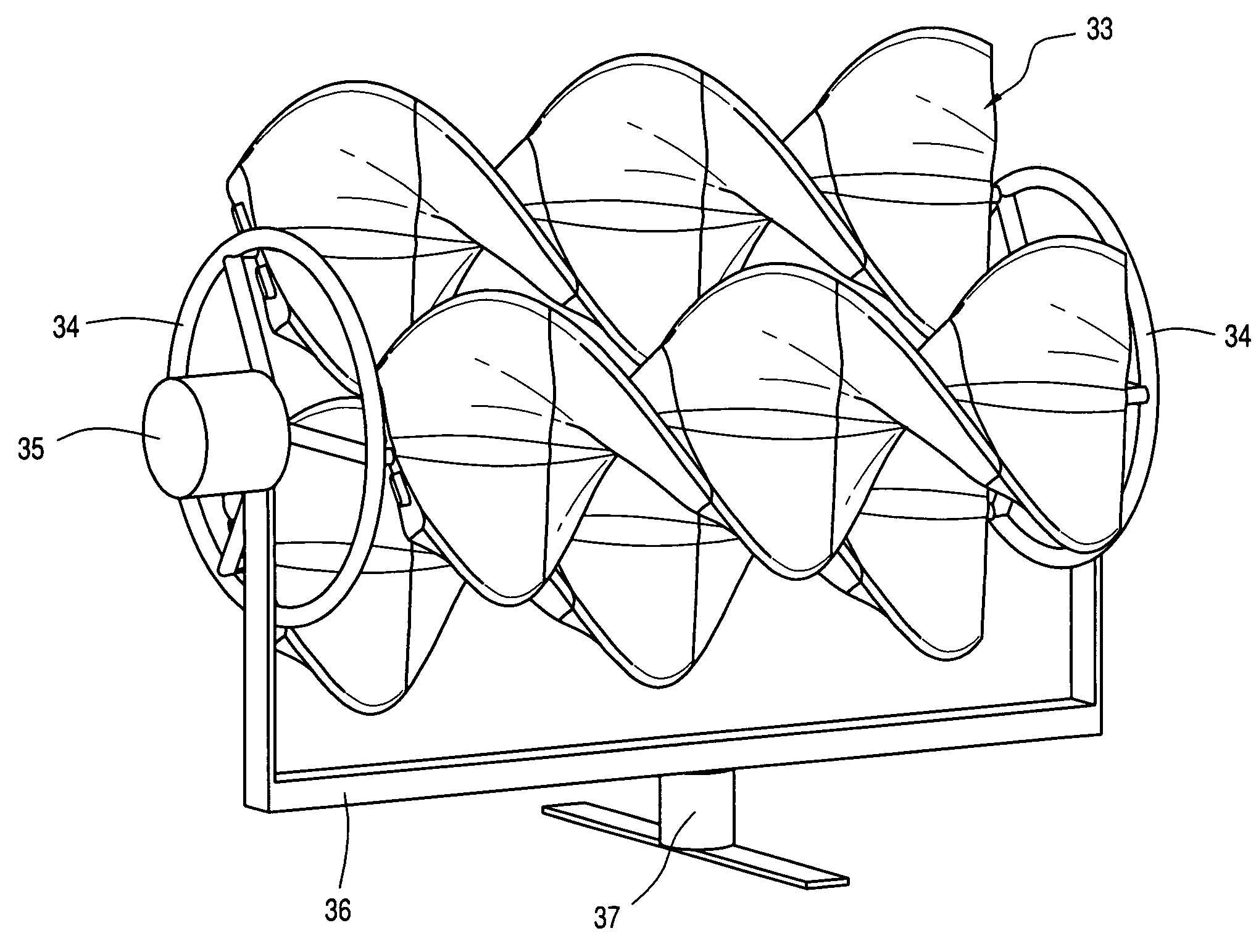
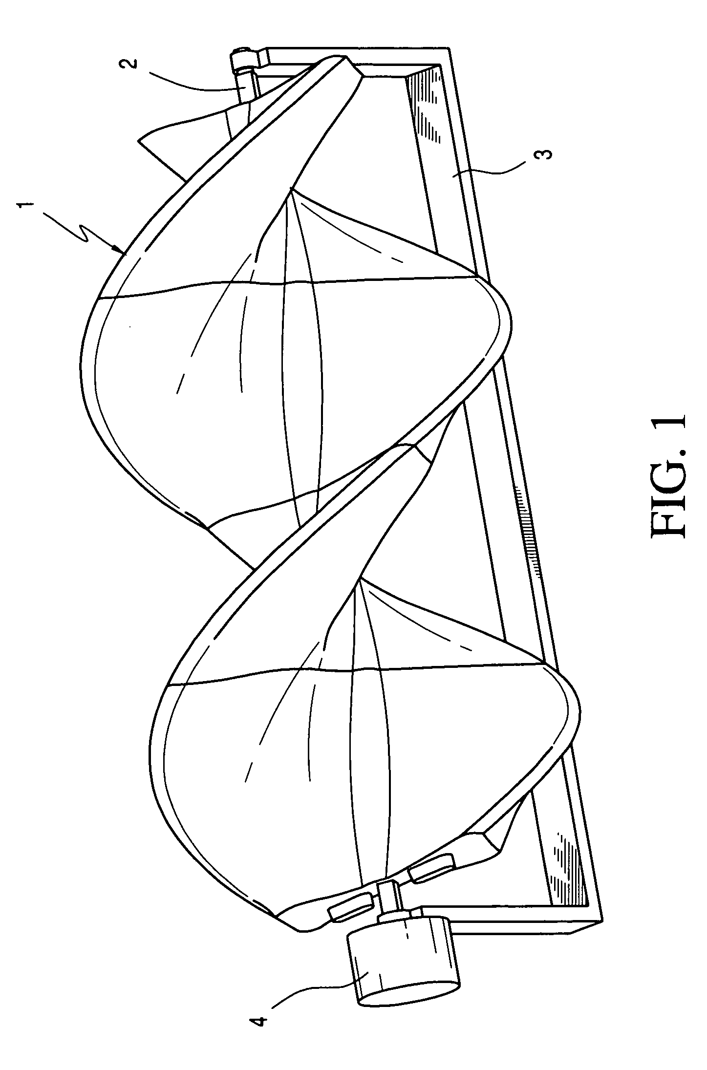
[0038]An assembly, built of multiple individual airfoil units 1 is shown in FIG. 1. This assembly is mounted on a center pole 2 that is attached to a frame 3 to which a generator 4 is attached. This design is a true airfoil design and thus it is always exposed to the wind regardless of wind direction. The airfoil of this invention provide a leading edge like an airplane wing and thus provides separation of the airflow between the top and bottom sections of the airfoil in such a manner that it generates lift in addition to being pushed. The combination of lift and push is not typical for conventional wind turbines and provides for improved efficiency.

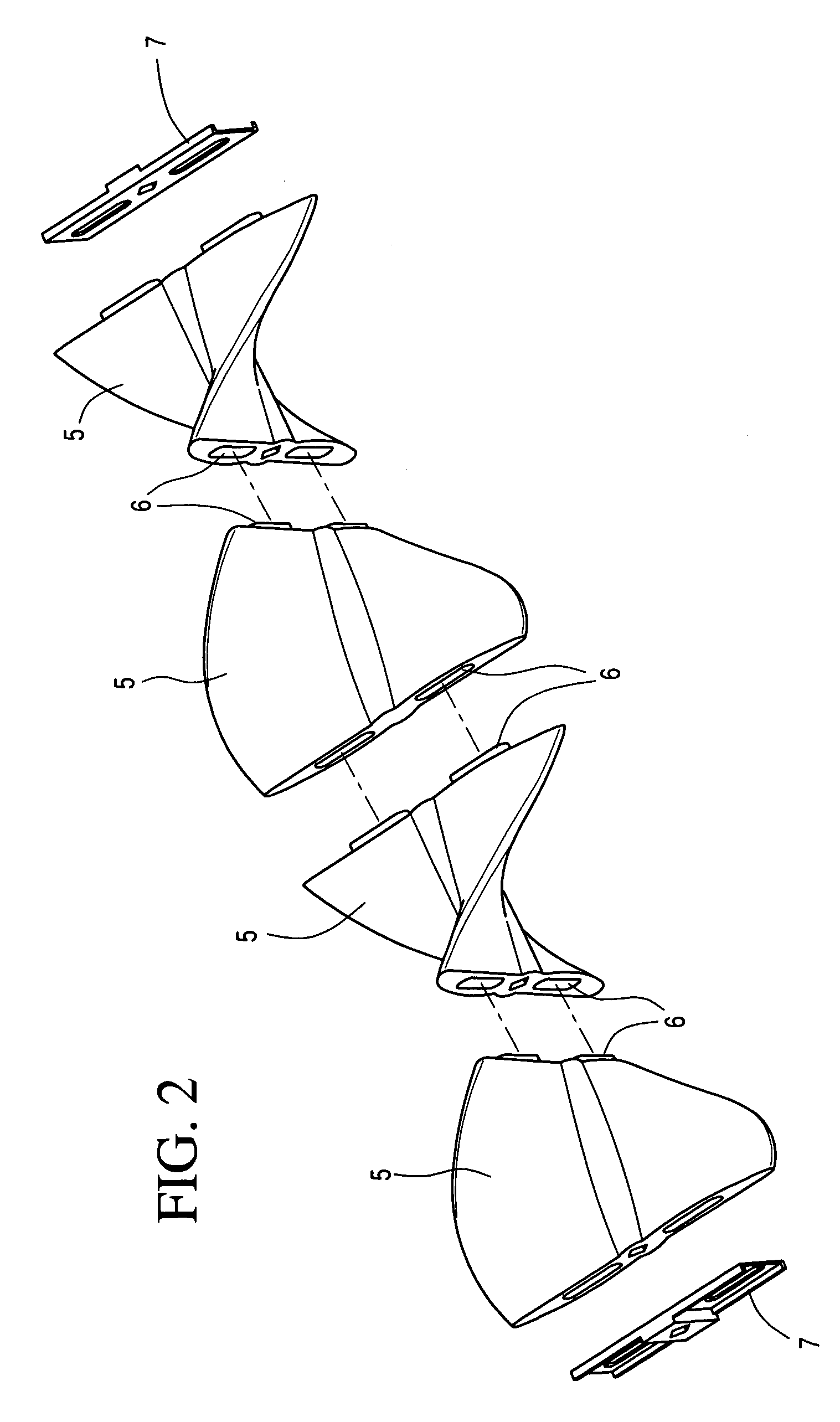
[0039]The twisted airfoil, shown in FIG. 2, is comprised of multiple units that stack upon each other until the desired size is formed. Shown are the individual unit 5, and the manner in which these units attach to each other 6. Also shown are optional metal end caps 7 that fit into the bosses on both ends and provide a strong attachment...


PUM


Abstract

An improved wind energy generator is described. This invention is a wind turbine that utilizes airfoils in unique designs that are made of lightweight materials. The turbine is manufactured by low cost production methods as portable units that are stacked in series to provide for significant power harvesting. The use of three dimensional twisted airfoils enable high efficiency and easy start up.

Description

CROSS-REFERENCE TO RELATED APPLICATION[0001]Not ApplicableSTATEMENT REGARDING FEDERALLY SPONSORED RESEARCH OR DEVELOPMENT[0002]Not ApplicableBACKGROUND OF THE INVENTION[0003]Many different types of wind turbines have been built that can efficiently convert wind energy into electrical energy. For large scale power generation, a typical configuration is a wind farm consisting of three bladed horizontal axis turbines. These turbines are very large with blades of 50-100 feet or more built upon large steel towers and are pointed into the wind. Alternatively, vertical axis wind turbines do not need to be pointed into the wind and have been built in many different designs. Many wind turbines have problems operating or starting up in low wind speed conditions, require complex mechanisms to adjust to wind conditions and can have problems with noise and vibration. Existing models are rarely suitable for congested urban conditions or portability and are not always suitable to be manufactured f...

Claims


Application Information

Patent Timeline
IPC IPC(8): F03D3/02F03D11/00
CPCF03D3/002F03D3/02Y02E10/74F05B2250/25Y02B10/30F03D3/061F05B2240/302Y02P70/50F03D9/25
Inventor SULLIVAN, JOHN T.
Owner SULLIVAN JOHN T
Why Eureka
Try Eureka