
Controlling Pumps for Improved Energy Efficiency

a technology of energy efficiency and control pump, applied in the direction of pump control, positive displacement liquid engine, non-positive displacement fluid engine, etc., can solve the problem that the pump may rarely operate at or near peak energy efficiency, and achieve the effect of reducing the size of the speed adjustmen

Active Publication Date: 2011-04-07
SPECIFIC ENERGY
View PDF11 Cites 59 Cited by
  • Summary
  • Abstract
  • Description
  • Claims
  • Application Information

AI Technical Summary

Benefits of technology

[0007]In some embodiments, the method may adjust the speed of the pump to fall only between a low speed threshold and a high speed threshold (referred to as clamping the speed of the pump). The method may also increase the size of the speed adjustment relative to a previous speed adjustment size...

Problems solved by technology

Pumps that respond to varying system demands (e.g., to attempt to maintain levels in elevated water tanks by transferring water from lower tanks) may rarely operate at or near peak energy efficiency.

Method used


Image

  • Controlling Pumps for Improved Energy Efficiency
  • Controlling Pumps for Improved Energy Efficiency
  • Controlling Pumps for Improved Energy Efficiency

Examples


embodiment

Illustrations

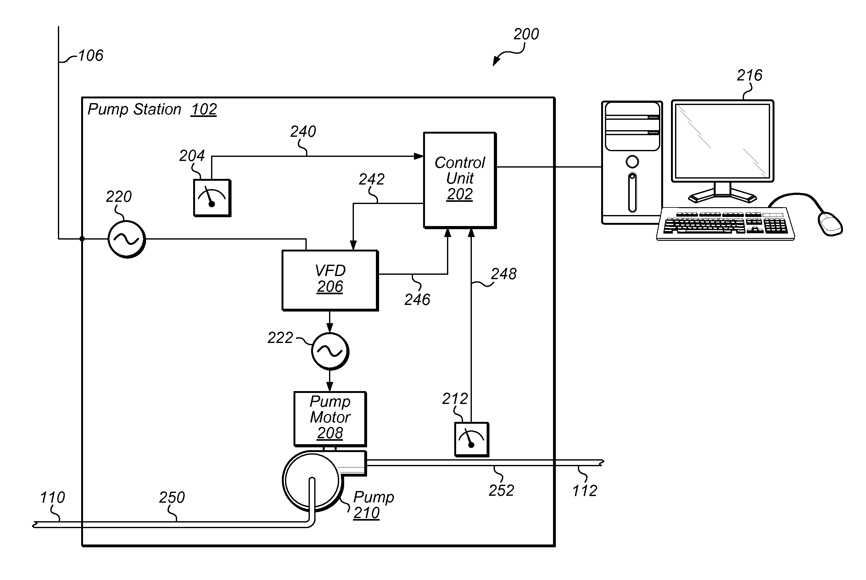
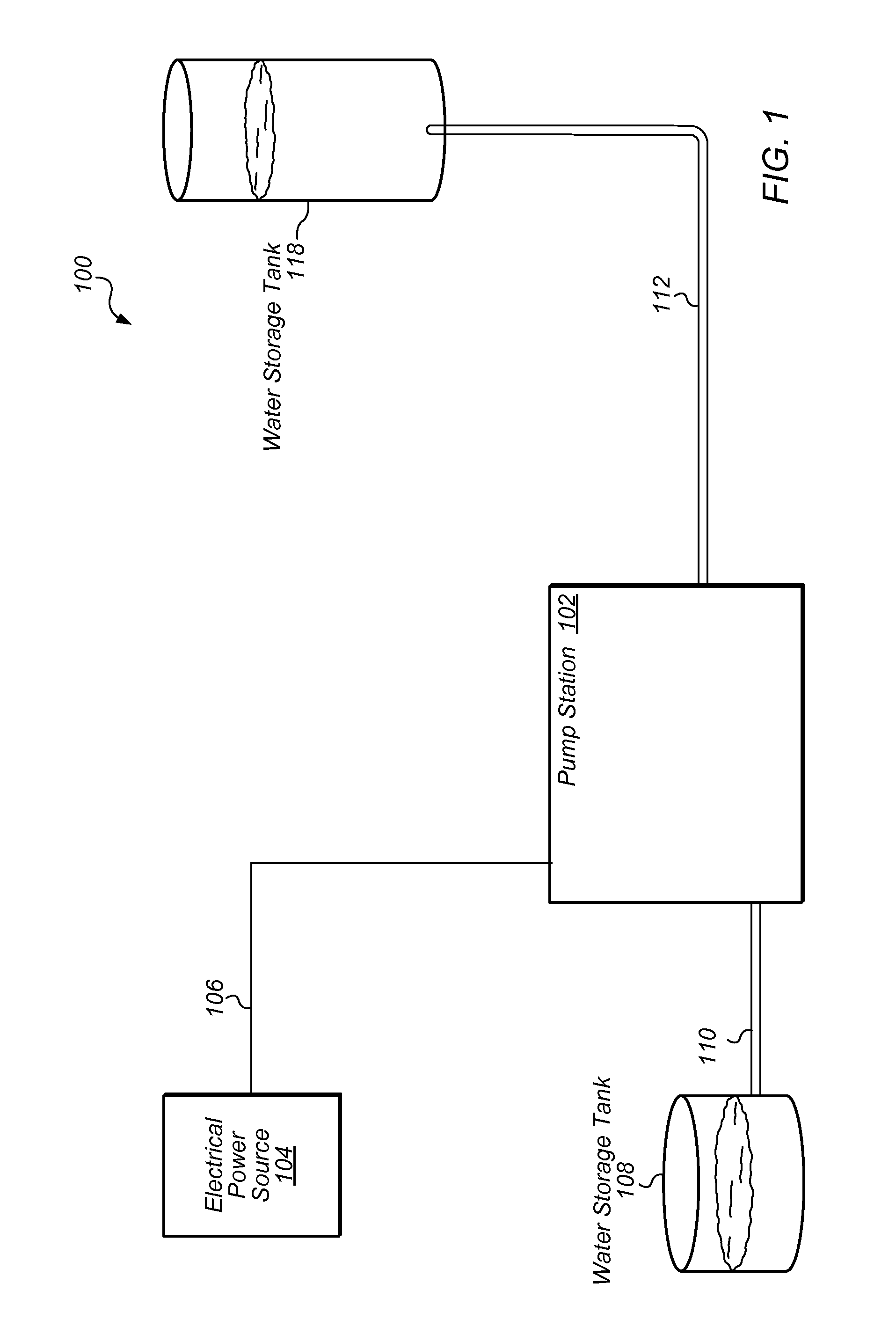
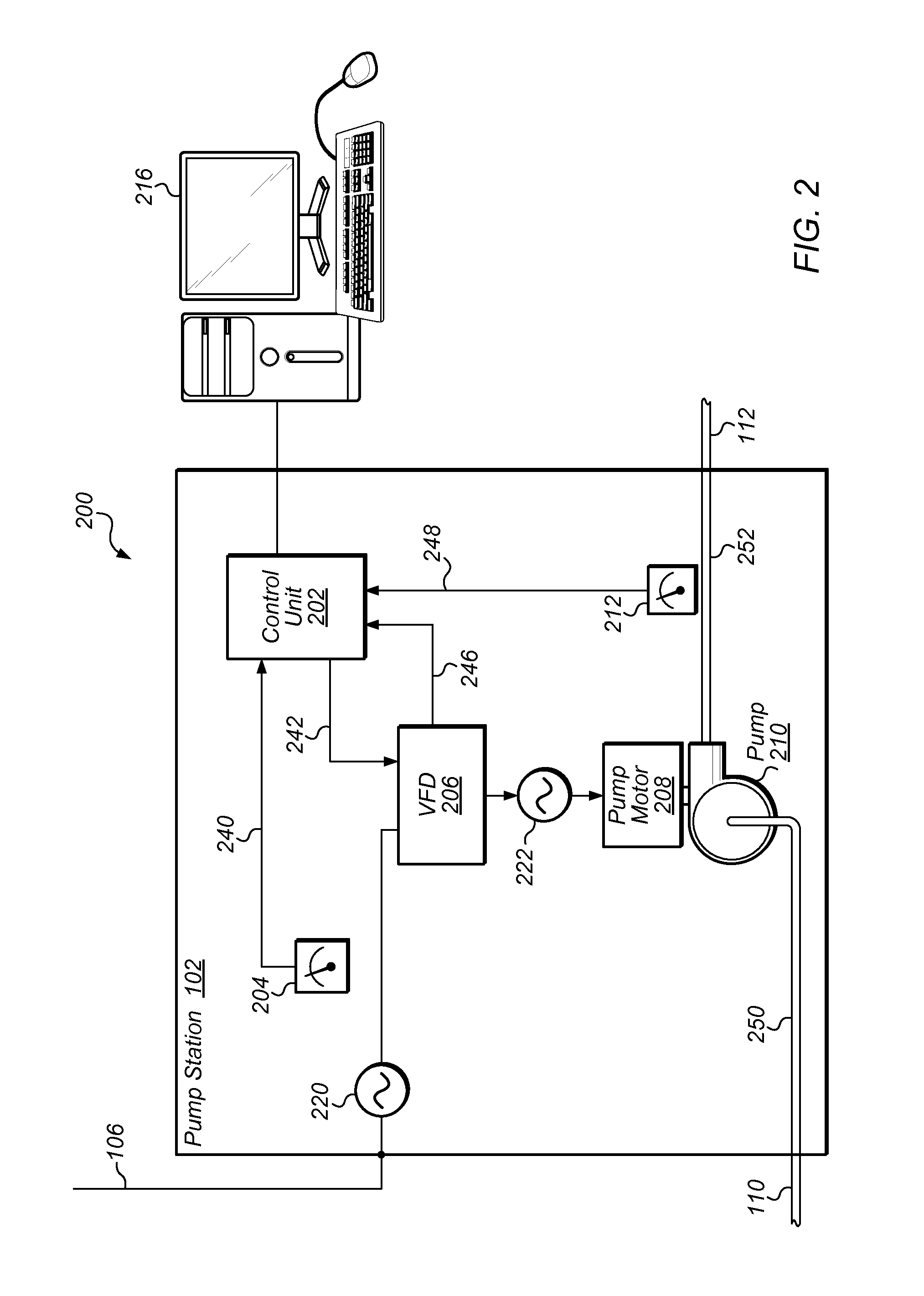
[0029]FIG. 1 illustrates an exemplary system which may utilize embodiments of the invention. FIG. 1 depicts a pumped water system 100 that includes a water pump station 102 supplied with electrical power via electrical supply line 106 from electrical power source 104. In the depicted embodiment, pump station 102 is connected, via piping 110 to storage tank 108. Pump station 102 is also connected via piping 112 to storage tank 118. Piping 110 and 112 may include relatively wide pipes, (e.g., 24 inch diameter pipes). Storage tank 108 may be a water storage tank (e.g., ground storage tank) that may hold a relatively large quantity of water (e.g., 2 million gallons (MG)) and may be relatively low in height (e.g., 35 feet tall) and may located at a moderate elevation (e.g., 915 feet above sea level). Storage tank 118 may also be a water storage tank (e.g., a mountain storage tank) that may also hold a relatively large quantity of water (e.g., 2 MG) and may be taller (e.g., 1...


PUM


Abstract

A method for improving the energy efficiency of a pump system. The method includes measuring an instantaneous power consumption of the pump system, measuring an instantaneous fluid flow rate of the pump system, and determining an instantaneous specific energy consumption (SEC) of the pump system based on the instantaneous power consumption and the instantaneous fluid flow rate. The method then adjusts the speed of a pump in response to the determined SEC. The above steps may be performed a number of times to seek a reduced value of the instantaneous SEC of the pump system.

Description

FIELD OF THE INVENTION[0001]This invention relates to a system and method of controlling pumps for the improvement of energy efficiency.DESCRIPTION OF THE RELATED ART[0002]According to a study commissioned by the US Department of Energy, pumping systems account for nearly 20% of the world's electrical energy demand and range from 25-50% of the energy usage in certain industrial plant operations. Electrical motor driven pumps may be used for water wells, water treatment plant raw water pumps, transfer pump stations, wastewater lift stations and a large variety of industrial applications that move fluids. Many of today's pumps are centrifugal pumps driven by AC induction motors. Typically, these induction motors operate at a fixed speed, based on the frequency of the AC power source. In the United States, 60 Hz power drives common synchronous AC induction motor speeds of 3600, 1800, 1200, and 900 rpm (rotations per minute). Variable frequency drives (VFDs) are becoming commonplace, an...

Claims


Application Information

Patent Timeline
IPC IPC(8): F04D15/00F04D13/02F04D13/06
CPCF04D15/0066
Inventor STEGER, PERRY C.PIERCE, DAVID MARK
Owner SPECIFIC ENERGY
Learn More