Dual enhanced tube for vapor generator

a technology of enhanced tubes and vapor generators, which is applied in the direction of indirect heat exchangers, heat generation using hot heat carriers, lighting and heating apparatus, etc., can solve the problems of reducing heat transfer and heat exchanger performance, and achieves improved heat transfer efficiency, increased heat transfer surface area, and improved heat transfer efficiency. effect of first zon

Inactive Publication Date: 2011-04-14
HAMON RES COTTRELL
View PDF14 Cites 30 Cited by
  • Summary
  • Abstract
  • Description
  • Claims
  • Application Information

AI Technical Summary

Benefits of technology

[0005]A heat exchanger assembly is used to transfer heat from a first medium to a second medium to convert the second medium from liquid to vapor. The vapor, or steam, is used to drive a steam turbine for generating electrical energy or for other processes such as desalination or mineral recovery. A tube is disposed inside the heat exchange assembly and includes an inner wall and an outer wall the length of which define a longitudinal axis. The outer wall includes a plurality of spaced fins oriented in a generally perpendicular manner to the longitudinal axis of the tube. The inner wall defines a preheat zone and a dual phase zone. The preheat zone defines a helical rib configured to provide swirling motion and increased heat transfer surface area to liquid entering the tube. The dual phase zone is spaced from the preheat zone and defines a helical rib configured to provide a swirling motion to the steam and liquid passing through the dual phase zone. In each instance, the helical rib improves the efficiency of heat transfer from the first medium to the second medium to convert liquid to steam.
[0006]The configuration of the inventive heat exchanger and dual enhanced tube is believed to provide heat exchange benefit for the specific purpose of converting liquid to vapor while meeting the demands of high-efficiency solar heat collector assemblies. By providing helical ribbing to the entry of a phase conversion tube, the efficiency of the first zone of the tube is improved to provide enhanced heat transfer from the first medium to the second medium while the second medium is still primarily in the liquid phase. In the zone before the outlet of the tube, where the second medium consists of high vapor fraction, the helical rib provides swirling turbulent motion to the vapor preventing vapor blanketing on the tube wall, which is known to cause reduced heat transfer as well as rapid scaling and fouling with deposits further resulting in the decrease of the performance of the heat exchanger. The dual enhanced tube provides the ability to increase the steam to liquid percentage to 20% without causing scaling inside the tube. This increased percentage over prior art tubes provides significant efficiency benefits. Therefore, the dual enhanced tube not only improves heat transfer efficiency, but also reduces the amount of maintenance and cleaning required of known steam generating systems.

Problems solved by technology

In the zone before the outlet of the tube, where the second medium consists of high vapor fraction, the helical rib provides swirling turbulent motion to the vapor preventing vapor blanketing on the tube wall, which is known to cause reduced heat transfer as well as rapid scaling and fouling with deposits further resulting in the decrease of the performance of the heat exchanger.

Method used


Image

  • Dual enhanced tube for vapor generator
  • Dual enhanced tube for vapor generator
  • Dual enhanced tube for vapor generator

Examples


Embodiment Construction

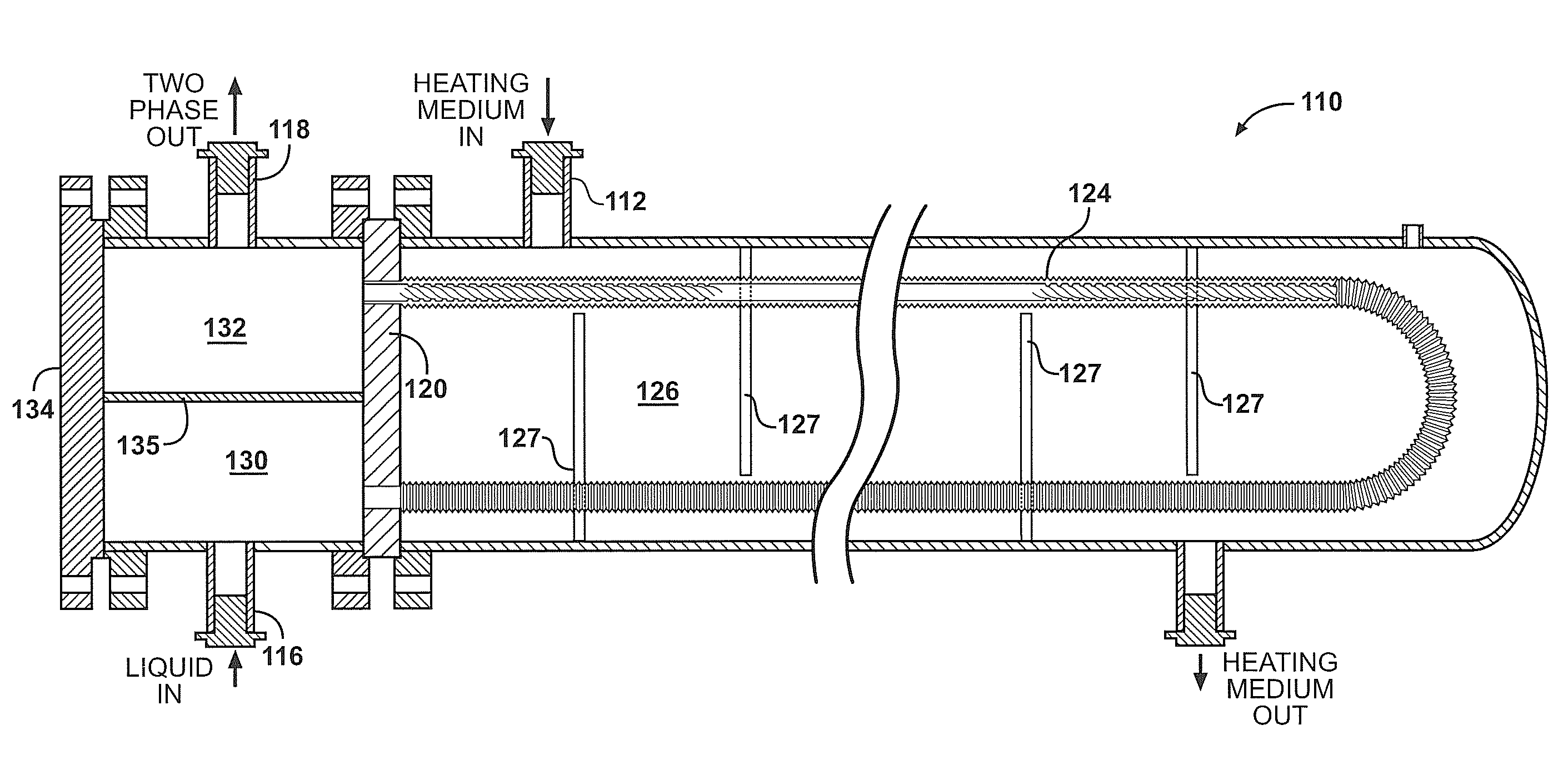
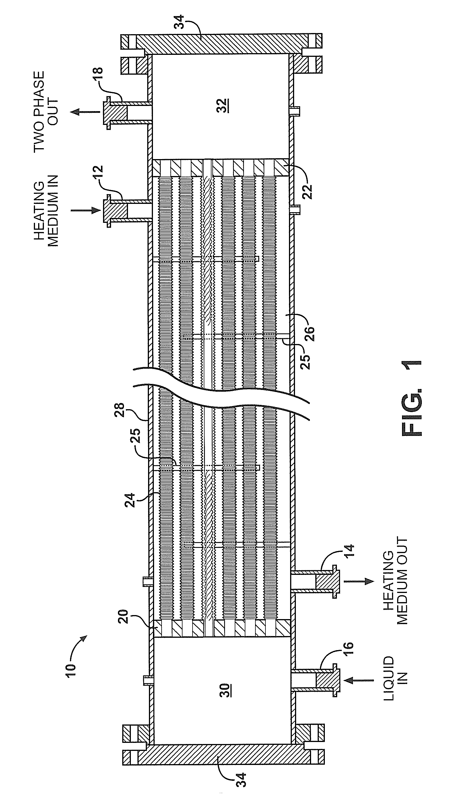
[0015]A heat exchanger assembly of the present invention is generally shown at 10 of FIG. 1. A first, or primary heating medium, enters the assembly 10 through heating medium inlet 12 and exits the assembly 10 through a heating medium outlet 14. The heating medium is contemplated by the inventors to be any liquid medium that is heated by an external energy source, for example, fossil fuel burning furnaces, nuclear energy reactors or solar energy collector fields. It is also contemplated by the inventors that the heating medium does not change phase, but remains in a liquid state throughout the process.

[0016]The second medium, or liquid, enters the assembly 10 through a liquid inlet 16 and exits the assembly 10 through a two phase flow outlet 18 after having been converted partially to vapor. It should be understood by those of skill in the art that the two phase flow will exit the assembly through the outlet 18. The second medium contemplated by the inventors is water that is conver...


PUM


Abstract

A heat exchange assembly for generating steam from a second medium to be used to drive a steam turbine for generating electricity or for other process, includes a tube having a longitudinal axis and an inner wall and an outer wall. The outer wall includes a plurality of spaced fins oriented generally perpendicular to the longitudinal axis. The inner wall defines a preheat zone and a dual phase zone. The preheat zone defines a helical rib configured to provide swirling motion and increase heat transfer surface area to liquid entering the tube increasing heat transfer from the tube to the liquid. The dual phase zone is spaced from the preheat zone and defines a helical rib configured to provide swirling motion to steam and liquid passing through the dual phase zone increasing heat transfer from the tube to the steam and liquid while preventing vapor stagnation and film boiling.

Description

BACKGROUND OF THE INVENTION[0001]The use of steam, for driving steam turbines for the purpose of generating electricity or for other processes such as desalination or enhanced mineral recovery, has been a common practice for many years. Various methods of generating steam have been employed making use of fossil fuels, nuclear fusion, and more recently, using solar energy. Generally, a heat exchanger having a primary liquid that is heated from the various sources set forth above heats a secondary liquid to generate steam.[0002]As the demands for steam for generating electricity and other recovery processes increase, it has become necessary to improve the heat transfer efficiency between primary and secondary mediums passing through a heat exchanger. Additionally, for improved solar plant economics, the immediate use of available solar energy has become very important, requiring optimized transfer of heat from the primary fluid to the secondary fluid during periods of solar field star...

Claims


Application Information

Patent Timeline
Patent Type & Authority Applications(United States)
IPC IPC(8): F22B1/02F28D1/04F28F1/10
CPCF22B1/16F22B15/00F22B21/30F28D7/06F28D7/16F28F1/26F28F2215/04F28F1/42F28F1/422F28F13/12F28F13/14F28F13/187F28F1/40
Inventor MASTER, BASHIR I.RANADE, BHUSHAN
Owner HAMON RES COTTRELL
Why Eureka
Try Eureka