
Monitoring system

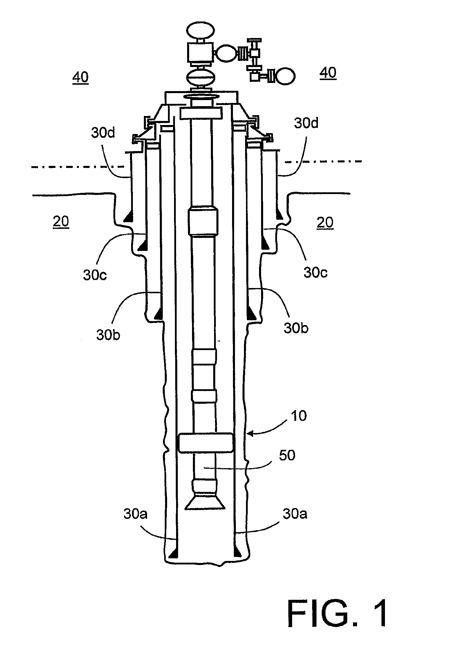
a monitoring system and monitoring technology, applied in the field of monitoring systems, can solve the problems of b>20/b> being potentially porous and susceptible to fragmentation, /i>itself being potentially susceptible to becoming obstructed, and b>20/b> being susceptible to being obstructed

Inactive Publication Date: 2011-04-14
BERGEN TECH CENT
View PDF1 Cites 28 Cited by
  • Summary
  • Abstract
  • Description
  • Claims
  • Application Information

AI Technical Summary

Benefits of technology

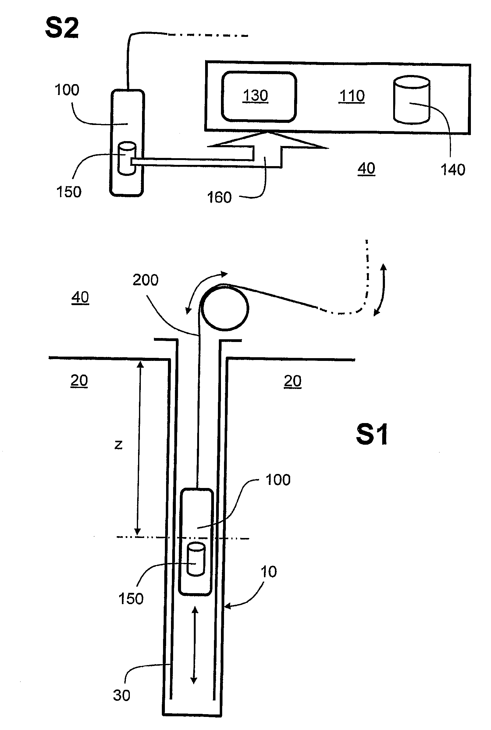
[0013]An object of the present invention is to provide an improved monitoring system which is operable to enable real-time monitoring of boreholes whilst also enabling spatial inspection of boreholes to be achieved.
[0019]The invention is of advantage in that preliminary processing executed within the digital signal processor is capable of reducing a quantity of measurement data to be communicated, thereby rendering possible real-time spatial monitoring of the borehole.
[0024]The first mode is of benefit in that it enables sources of noise, for example leakage holes, failed seals, cracks and other types of defect through which fluids are capable of flowing and generating acoustic noise, to be detected.
[0026]Optionally, the system is operable to communicate data bi-directionally between the data processing arrangement and the probe assembly, wherein the digital signal processor of the probe assembly is operable to be reconfigured between a first function of generally sensing around in a region of the borehole in a vicinity of the probe assembly, and a second function of specific sensing in a sub-region of the region of the borehole in a vicinity of the probe assembly. Bi-directional communication enables the probe assembly to be reconfigured to occasionally concentrating on sensing certain sub-regions of the borehole of special interest, thereby using finite communication bandwidth provided by the communication link in an efficient manner.
[0032]Optionally, the system is implemented such that the data communication link comprises one or more twisted-wire pairs including plastics material insulation and copper electrical conductors embedded within the plastics material, the data communication link being clad by cladding susceptible to bearing a weight of the probe assembly when the assembly is moved in operation within the borehole. Use of twisted pairs is of benefit in providing a reliable and stable line impedance for electrical signals and thereby substantially avoiding end reflections of electrical signals when appropriately-matched line drivers and receivers are employed, whilst providing a mechanically robust implementation when the probe assembly is manoeuvred in the borehole.

Problems solved by technology

Furthermore, the region of ground 20 is potentially porous and susceptible to fragmenting into quantities of gravel and similar types of sand particles.
Many practical problems are often encountered when drilling the borehole 10; moreover, subsequent problems can arise when extracting oil and / or gas via the borehole 10.
Moreover, the liner tube 30a itself is potentially susceptible to becoming obstructed with deposits transported up the liner tube 30a, for example sand / oil / tar deposits.
When aforementioned one or more leakage holes and / or obstructions occur many kilometres underground, it is often very difficult to know at an above-ground region 40 what precisely is happening in the ground 20 in respect of the borehole 10.
However, physical conditions within the borehole 10, for example in lower regions thereof, are very hostile on account of abrasive particles present, high ambient temperatures in an order of 150° C. or more, high pressure approaching 1000 Bar and corrosive and / or penetrative fluids present in the borehole 10.
A technical problem is encountered when the probe assembly 100 in FIG. 2 is employed to spatially inspect, for example by employing one or more optical cameras, an inside of a borehole 10 on account of a considerable amount of corresponding data which is generated.

Method used


Image

  • Monitoring system
  • Monitoring system
  • Monitoring system

Examples


Embodiment Construction

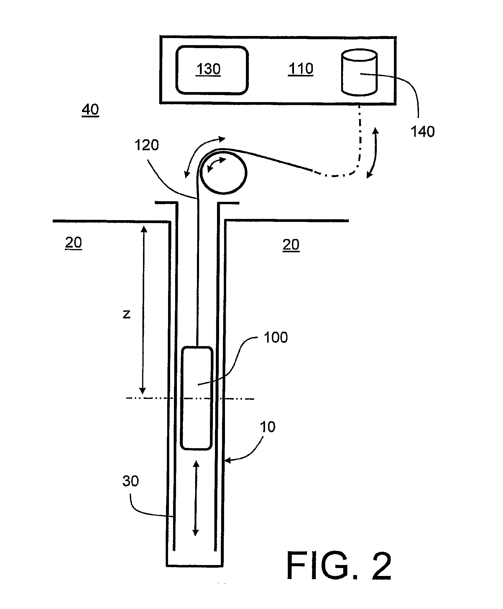
[0073]In overview, embodiments of the present invention include principal features akin to FIG. 2, namely:[0074](a) a probe assembly 100 for spatially sensing within a borehole 10;[0075](b) a communication link 120 whose associated cladding or mechanical structural core is operable to mechanically support the probe assembly 100 when deployed within the borehole 10, and whose signal guiding components are operable to convey signals transmitted from the probe assembly 100, and to convey control signals to the probe assembly 100;[0076](c) a data processing arrangement 110 coupled via the communication link 120 to the probe assembly 100, the data processing arrangement 110 being operable to receive signals from the probe assembly 100 and to send instruction signals to the probe assembly 100.

[0077]The probe assembly 100, the communication link 120 and the data processing arrangement 110 constitute a system as denoted by 300 in FIG. 4; the system 300 constitutes an embodiment of the prese...


PUM


Abstract

There is provided a monitoring system (300) for monitoring within a borehole (10). The system (300) comprises a probe assembly (100) operable to be moved within the borehole (10) for sensing one or more physical parameters therein, a data processing arrangement (110) located outside the borehole (10), and a data communication link (120) operable to convey sensor data indicative of the one or more physical parameters from the probe assembly (100) to the data processing arrangement (110) for subsequent processing and display and / or recording in data memory (140). The probe assembly (100) includes one or more sensors (320) for spatially monitoring within the borehole (10) and generating corresponding sensor signals (360). Moreover, the probe assembly (100) includes a digital signal processor (310) for executing preliminary processing of the sensor signals (360) to generate corresponding intermediately processed signals (370) for communication via the data communication link (120) to the data processing arrangement (110). Furthermore, the data processing arrangement (110) is operable to receive the intermediately processed signals (370) and to perform further processing on the intermediately processed signals (370) to generate output data for presentation (130) and / or for recording in a data memory arrangement (140). The system (300) is of benefit in that it enables real-time spatial monitoring of the borehole (10) to be achieved.

Description

FIELD OF THE INVENTION [0001]The present invention relates to monitoring systems, for example to monitoring systems for monitoring boreholes in connection with oil and / or gas exploration and / or extraction. Moreover, the present invention is concerned with methods of monitoring boreholes in connection with oil and / or gas exploration and / or extraction. Furthermore, the present invention also relates to software products for use in implementing these aforesaid methods.BACKGROUND OF THE INVENTION[0002]Referring to FIG. 1, a borehole indicated generally by 10 is formed in a region of ground 20 during gas and / or oil exploration. In an event that deposits of oil and / or gas are found substantially at an end of the borehole 10, the borehole 10 provides a route by which the oil and / or gas deposits can be subsequently extracted. The borehole 10 is often several kilometres in depth and filled with liquid, for example:[0003](a) with drilling mud when executing boring operations during oil and / or...

Claims


Application Information

Patent Timeline
Patent Type & Authority Applications(United States)
IPC IPC(8): G06F19/00G01V5/00E21B47/00E21B47/12
CPCE21B47/0002E21B47/0003E21B47/12G01N2291/106G01N29/14G01N29/245G01N29/043E21B47/003E21B47/002E21B47/0025
Inventor LIE, TERJE LENNART
Owner BERGEN TECH CENT
Learn More