Gas turbine engine temperature modulated cooling flow

Active Publication Date: 2011-04-21
GENERAL ELECTRIC CO
View PDF26 Cites 163 Cited by
  • Summary
  • Abstract
  • Description
  • Claims
  • Application Information

AI Technical Summary

Benefits of technology

[0011]Accordingly, it is desired to provide a gas turbine e

Problems solved by technology

Any air used for turbine cooling is lost from the combustion cycle and, therefore, reduces overall efficiency of the

Method used


Image

  • Gas turbine engine temperature modulated cooling flow
  • Gas turbine engine temperature modulated cooling flow
  • Gas turbine engine temperature modulated cooling flow

Examples


Embodiment Construction

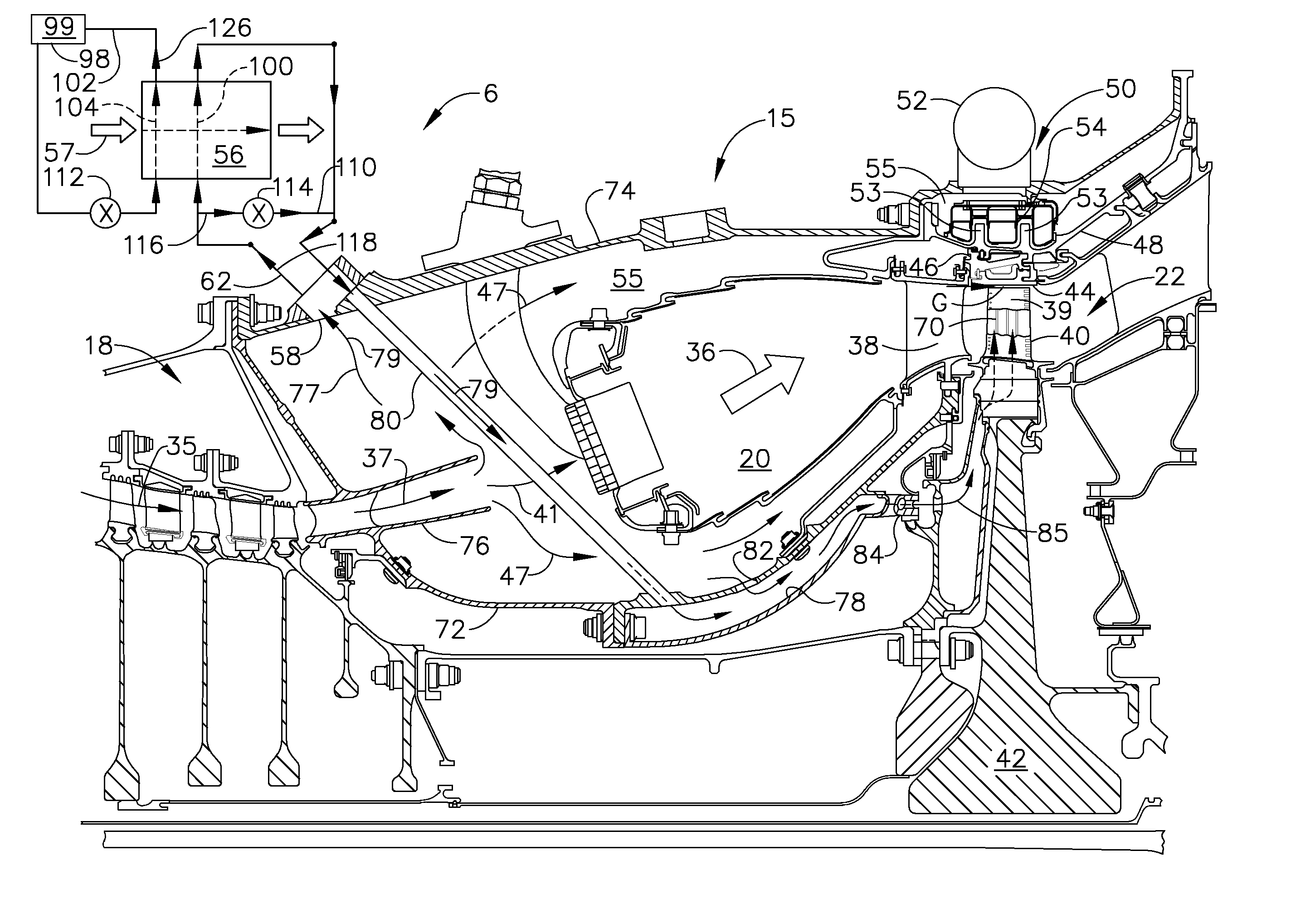
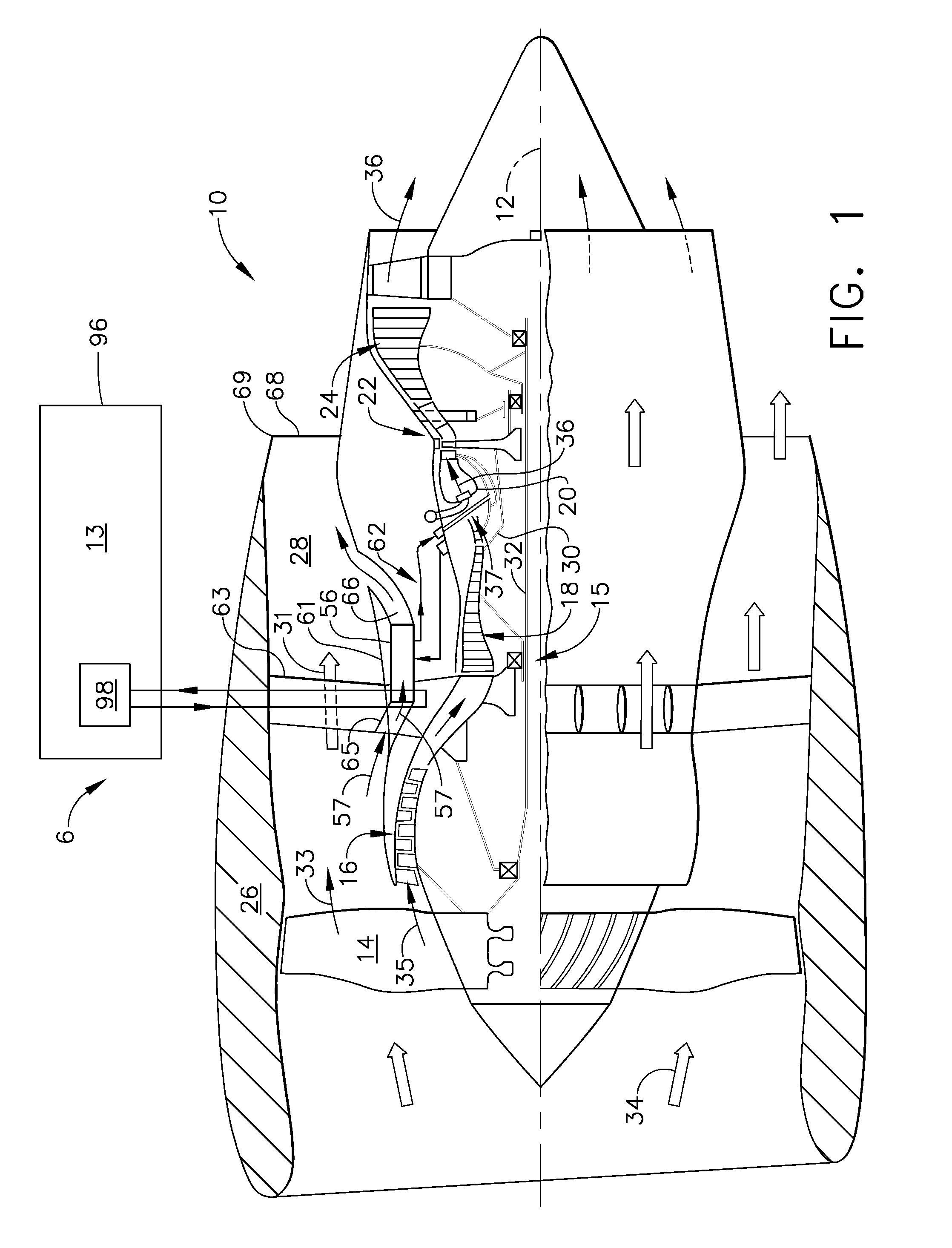
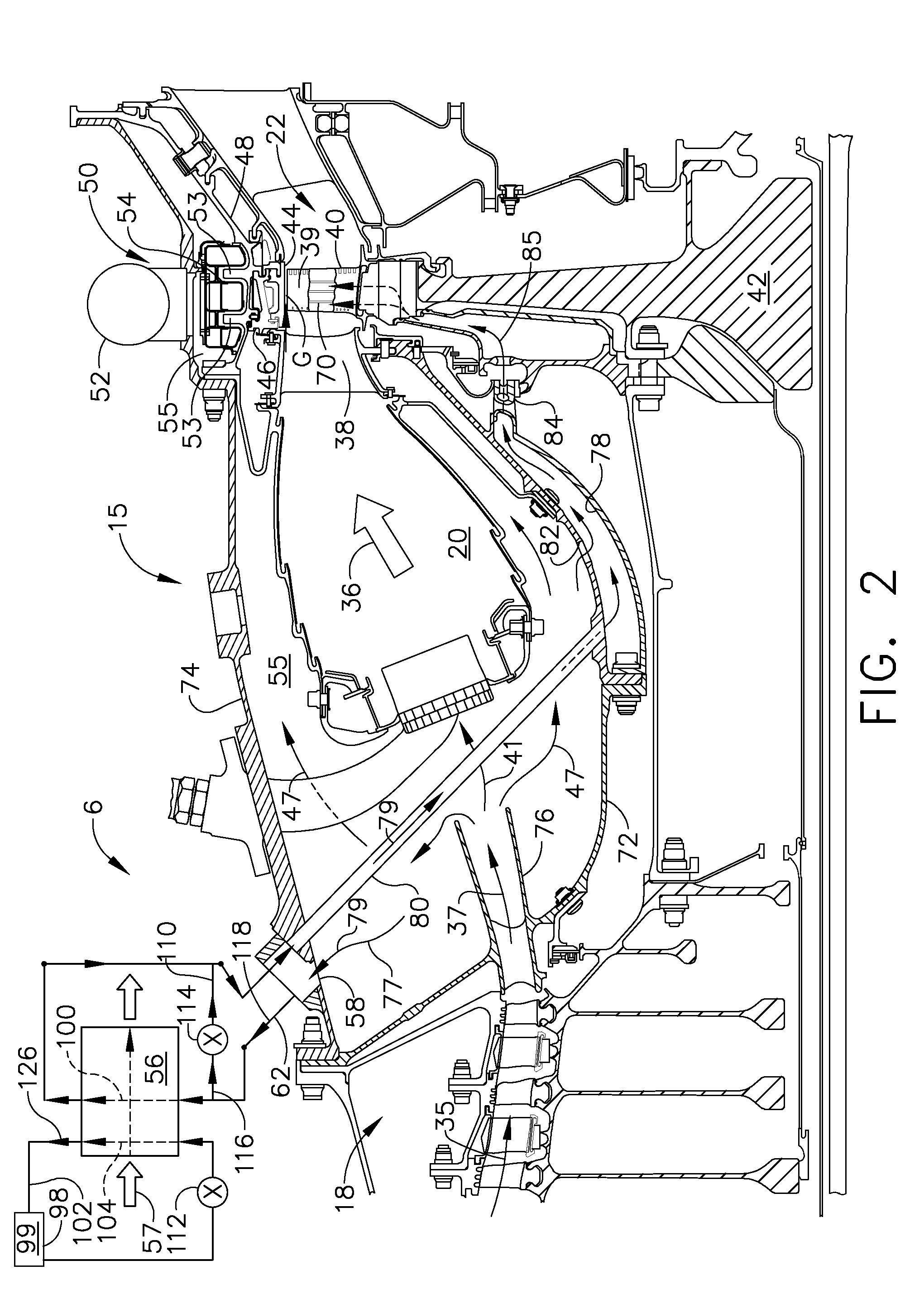
[0023]Illustrated schematically in FIG. 1 is an exemplary turbofan aircraft gas turbine engine 10. The engine 10 is axisymmetrical about a longitudinal or axial centerline axis 12 and is suitably mounted to the wing or a fuselage of an aircraft 13. The engine includes in serial flow communication a fan 14, a low pressure or booster compressor 16, a high pressure (HP) compressor 18, an annular combustor 20, a high pressure turbine (HPT) 22, and a low pressure turbine (LPT) 24. An annular nacelle 26 surrounds the fan 14 and defines an annular bypass duct 28 extending aft around the booster compressor 16. A first drive shaft 30 joins the HPT 22 to the HP compressor 18, and a second drive shaft 32 joins the LPT 24 to the fan 14 and booster compressor 16. A core engine 15 typically includes, in downstream serial flow communication, the high pressure compressor 18, the annular combustor 20, and the HPT 22.

[0024]During operation, ambient air 34 enters the inlet of the engine and is pressur...


PUM


Abstract

A gas turbine engine cooling system includes a heat exchanger in fluid communication with a source of cooling air, a first cooling circuit including a first heat exchanger circuit in the heat exchanger and a first bypass circuit with a first bypass valve for selectively bypassing at least a portion of first airflow around the first heat exchanger circuit. A second cooling circuit may be used having a second heat exchanger circuit in the heat exchanger and a shutoff control valve operably disposed in the second cooling circuit upstream of the second heat exchanger circuit and the heat exchanger. A circuit inlet of the first cooling circuit may be used to bleed a portion of compressor discharge bleed air for the first airflow to cool turbine blades mounted on a rotor disk using an annular flow inducer downstream of the first bypass valve and the heat exchanger.

Description

BACKGROUND OF THE INVENTION[0001]1. Technical Field[0002]The present invention relates generally to gas turbine engine cooling flows and, more specifically, to modulating cooling flows for turbine components and for airframe heat loads.[0003]2. Background Information[0004]A typical gas turbine engine of the turbofan type generally includes a forward fan and a booster or low pressure compressor, a middle core engine, and a low pressure turbine which powers the fan and booster or low pressure compressor. The core engine includes a high pressure compressor, a combustor and a high pressure turbine (HPT) in a serial flow relationship. The high pressure compressor and high pressure turbine of the core engine are connected by a high pressure shaft. High pressure air from the high pressure compressor is mixed with fuel in the combustor and ignited to form a high energy gas stream. The gas stream flows through the high pressure turbine, rotatably driving it and the high pressure shaft which,...

Claims


Application Information

Patent Timeline
IPC IPC(8): F02C7/18
CPCF01D5/081F02C7/185Y02T50/676Y02T50/671F02K3/115Y02T50/60F01D25/12F02C7/18
Inventor TURCO, JOHN BIAGIO
Owner GENERAL ELECTRIC CO
Why Eureka
Try Eureka