Showerhead assembly for plasma processing chamber

a plasma processing chamber and plasma technology, applied in applications, manufacturing tools, other domestic objects, etc., can solve the problems of affecting the quality of the process, increasing the difficulty of controlling the uniformity of deposited films, and increasing the difficulty of batch processing, so as to improve the gas distribution and facilitate the manufacturing process. , the effect of significantly less cos

Active Publication Date: 2011-04-21
KLA TENCOR TECH CORP
View PDF20 Cites 89 Cited by
  • Summary
  • Abstract
  • Description
  • Claims
  • Application Information

AI Technical Summary

Benefits of technology

[0009]Embodiments of the invention provide a showerhead assembly that is easier and significantly less expensive to manufacture, while having improved gas distribution. Showerheads made according to embodiments of the invention do not require the drilling of large number of small diameter holes. Embodiments of the invention also do not require complex hole shapes. Instead, control over gas distribution gradient or uniformity is done using a baffle plate. A se

Problems solved by technology

Some of the issues considered in designing a showerhead include proper mixing of the gas, control over the distribution of the gas throughout the chamber, control over the temperature of the showerhead and gases within the showerhead, pitting of the showerhead by plasma species, rate of gas delivery, complexity and cost of production, and more.
The design of the showerhead assembly is critical, as it directly affects the quality of the process in the plasma chamber.
Uniformity of deposited film becomes more difficult to control as the size of the substrate increases, for example when processing large substrates for LCD or thin-film solar panels.
Uniformity is also more difficult to control when performing batch processing, i.e., when forming film on several substrates concurrently in the same chamber.
However, as is evident these d

Method used


Image

  • Showerhead assembly for plasma processing chamber
  • Showerhead assembly for plasma processing chamber
  • Showerhead assembly for plasma processing chamber

Examples


Embodiment Construction

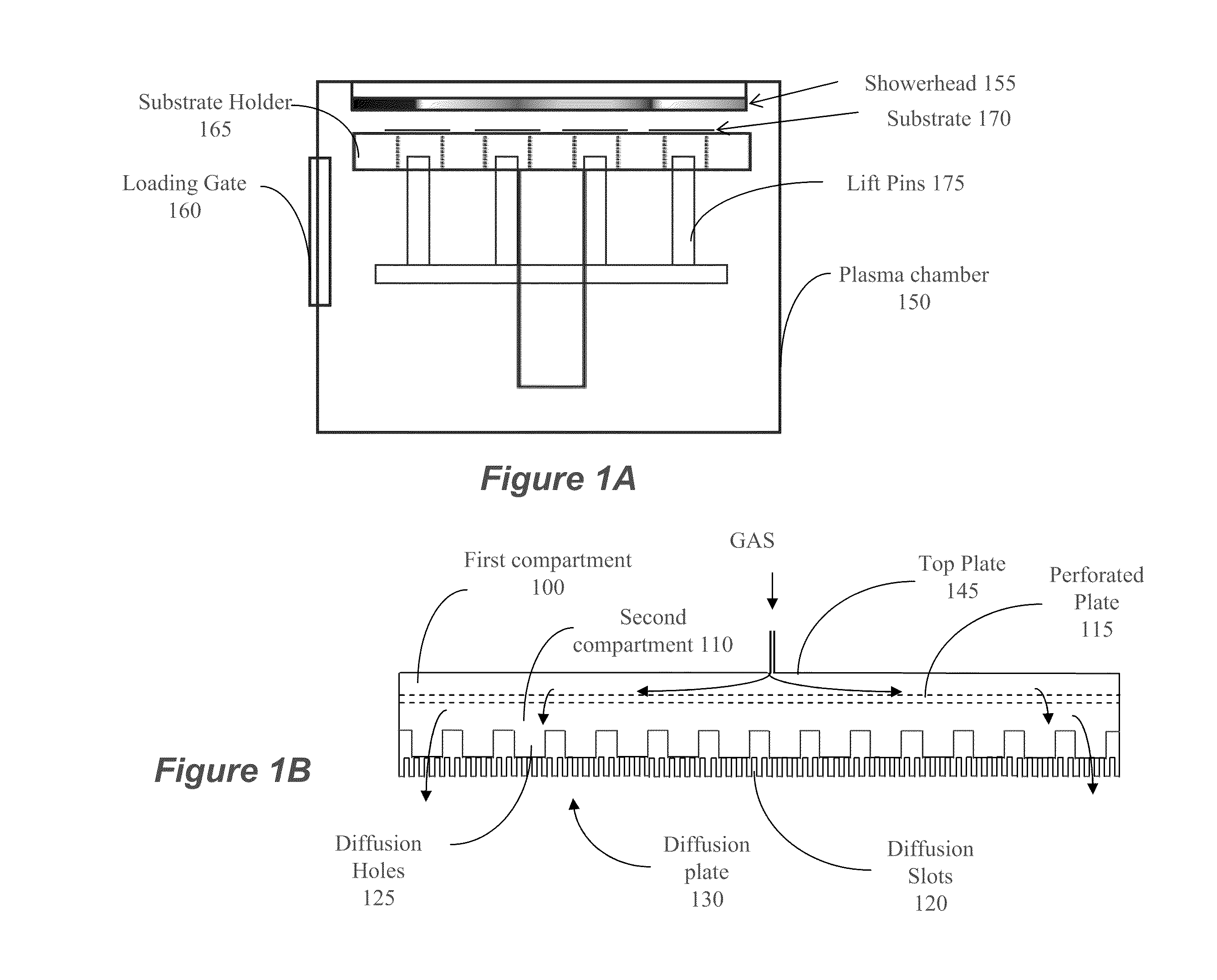
[0025]FIG. 1A illustrates a plasma processing chamber 150 that may incorporate a showerhead 155 according to the invention. In this example the chamber 150 includes a loading gate 160 for loading and unloading substrates. A substrate holder 165 may be a simple holder, a holder incorporating a heater, a chuck, such as, e.g., an electrostatic chuck, etc. The substrate holder 165 may hold a single substrate or a plurality of substrates. In this example, the holder supports a plurality of substrates 170, each of which may be lifted from the holder 165 using lift pins 175. Also, the showerhead 155 may be coupled to the ground or RF potential of an RF generator, e.g., via an impedance match circuit (not shown).

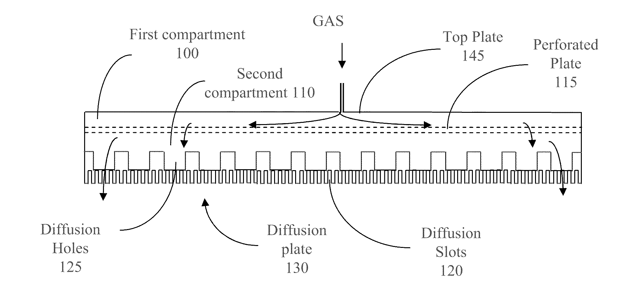
[0026]FIG. 1B is a schematic illustrating in a cross section showing major elements of a showerhead according to an embodiment of the invention. In this particular example the showerhead is rectangular, but other shape can be used, depending on the shape of the plasma chamber. Since...


PUM

PropertyMeasurementUnit
Diameteraaaaaaaaaa
Widthaaaaaaaaaa
Depthaaaaaaaaaa

Abstract

A showerhead for a plasma process apparatus for processing substrates, comprising a showerhead body comprising a top plate and a bottom plate defining a cavity in between; a gas inlet formed in the top plate; a perforated plate positioned between the top plate and the bottom plate and dissecting the cavity into an upper gas compartment and a lower gas compartment; and, wherein the bottom plate comprises a plurality of elongated diffusion slots on its lower surface and a plurality of diffusion holes on its upper surface, each of the diffusion holes making fluid connection from the lower gas compartment to more than one of the diffusion slots.

Description

RELATED APPLICATION[0001]This application claims priority benefit from U.S. Provisional Patent Application No. 61 / 252,117, filed Oct. 15, 2009, the disclosure of which is incorporated herein by reference in its entirety.BACKGROUND[0002]1. Field of the Application[0003]The invention relates to showerheads for plasma processing chambers, such as for Chemical Vapor Deposition (CVD), Plasma Enhanced Chemical Vapor Deposition (PECVD), and etching of films.[0004]2. Related Art[0005]Apparatus of plasma processing, such as, e.g., plasma enhanced chemical vapor deposition of films, utilize showerhead to introduce the gases into the chamber. Various showerheads for plasma chambers are known in the art. The showerhead delivers processing gas into the plasma processing chamber. Some of the issues considered in designing a showerhead include proper mixing of the gas, control over the distribution of the gas throughout the chamber, control over the temperature of the showerhead and gases within t...

Claims


Application Information

Patent Timeline
IPC IPC(8): C23F1/08C23C16/00C23C16/455B23B35/00
CPCC23C16/45565H01J37/32449C23C16/50H01J37/3244Y10T408/03C23C16/45578Y10T29/49428H01J37/32091Y10T29/496H01L21/205H01L21/02274H01L21/0228H01L21/02315
Inventor LAW, KAM S.TOSHIMA, MASATOBLONIGAN, WENDELL THOMASCAN, LINHLAW, ROBIN K. F.
Owner KLA TENCOR TECH CORP
Why Eureka
Try Eureka