Electro-mechanical transducer, method of making the transducer, liquid ejection head including the transducer, and liquid ejection apparatus including the head

a transducer and electromechanical technology, applied in piezoelectric/electrostrictive transducers, generators/motors, device material selection, etc., can solve the problems of reducing reliability, deteriorating electromechanical properties, and reducing fatigue resistan

Active Publication Date: 2011-04-21
RICOH KK
View PDF2 Cites 31 Cited by
  • Summary
  • Abstract
  • Description
  • Claims
  • Application Information

AI Technical Summary

Problems solved by technology

Such an electrode may deteriorate due to dispersion of lead (Pb) contained in PZT, which may degrade fatigue resistance.
Further, the desired cohesion of the metal electrode with the piezoelectric layer may not be obtained, causing reduced reliability.
Consequently, when the plurality of piezoelectric elements is simultaneously driven to eject a large number of ink droplets at a time, the resulting voltage drop can destabilize the degree of displacement of the independent piezoelectric elements, thus degrading ink ejection characteristics.

Method used


Image

  • Electro-mechanical transducer, method of making the transducer, liquid ejection head including the transducer, and liquid ejection apparatus including the head
  • Electro-mechanical transducer, method of making the transducer, liquid ejection head including the transducer, and liquid ejection apparatus including the head
  • Electro-mechanical transducer, method of making the transducer, liquid ejection head including the transducer, and liquid ejection apparatus including the head

Examples


example 1

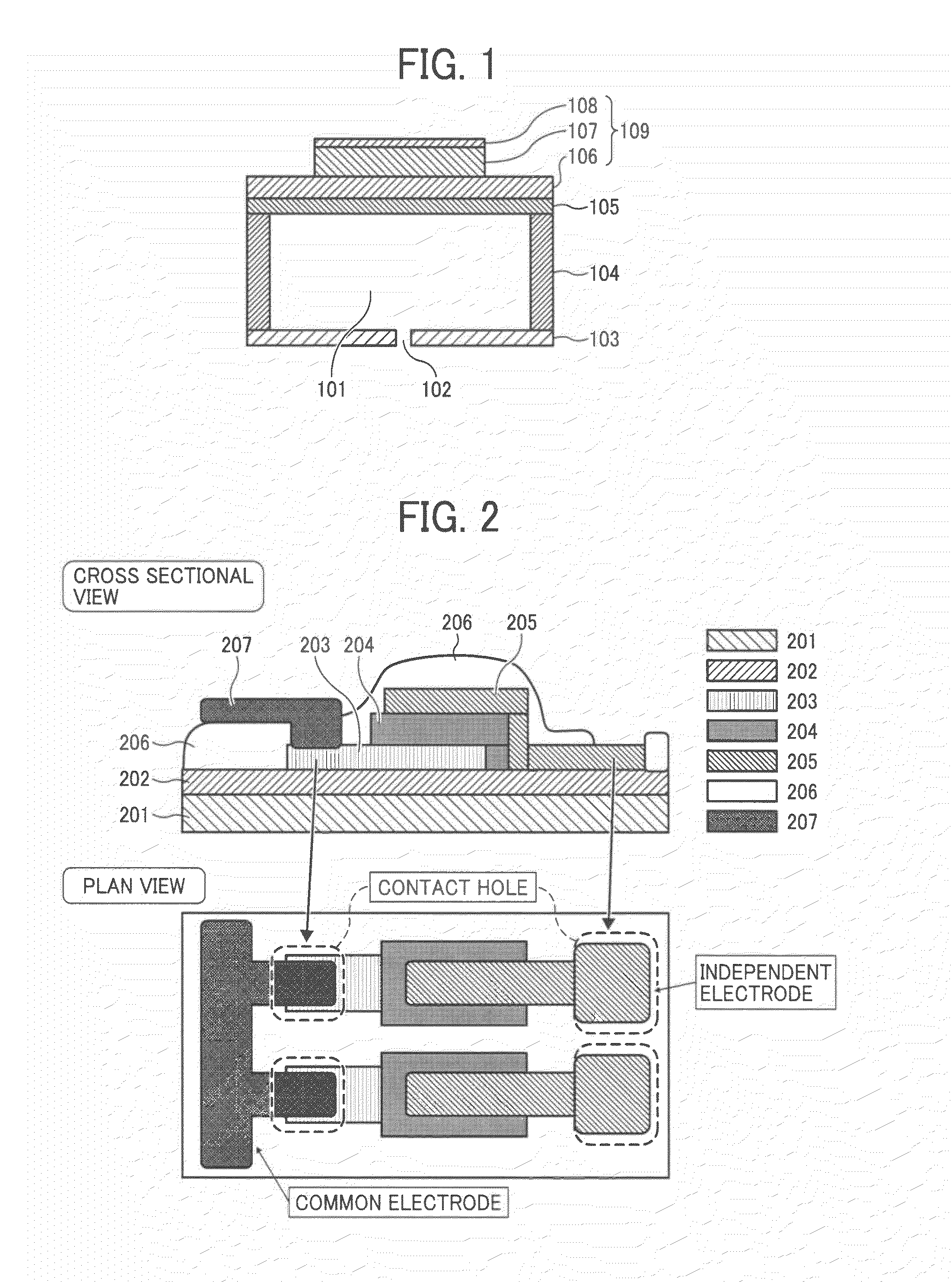
[0129]A thermally-oxidized film having a thickness of 1 μm is formed on a silicon wafer, and a SrRuO3 film having a thickness of 200 μm is formed on the thermally-oxidized film by sputtering to form a first electrode. Then, a photoresist (for example, TSMR8800 manufactured by TOKYO OHKA KOGYO Co., Ltd.) is coated by spin coating and patterned by standard photolithographic processing. Then, a pattern as illustrated in FIG. 2 is formed by an inductively coupled plasma (ICP) etching apparatus (manufactured by, for example, SAMCO Inc.).

[0130]Using octa-(C8)-trychlorosilane (OTS) as a silane compound, the wafer is immersed in a solution (solvent: ethanol) of a concentration of 0.01 mol / l, thereby performing SAM treatment. Then, the wafer is washed with ethanol and dried, and the process goes to the patterning steps illustrated in FIG. 6.

[0131]The hydrophobic property after SAM treatment is determined by measuring contact angle. A contact angle of water on the SAM film is, for example, 10...

example 2

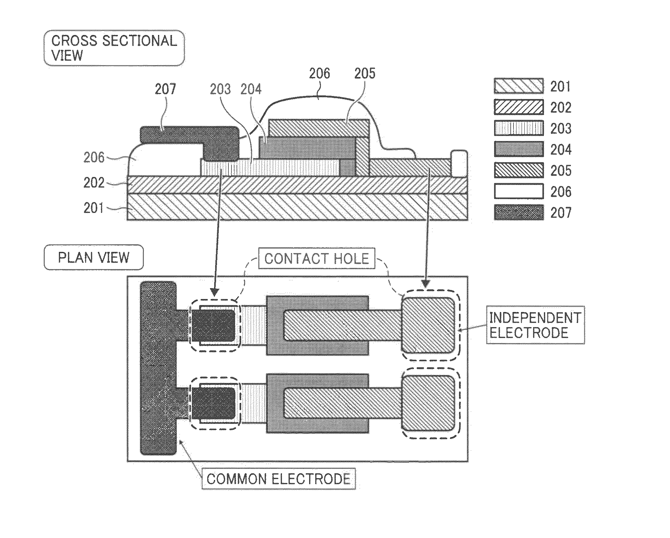
[0146]The process up to the formation of the second electrode is performed in a way similar to, if not the same as, the above-described way of Example 1. Then, an Al film of a thickness of, for example, 5 μm is formed as a third electrode by sputtering. Further, a photoresist (for example, TSMR8800 manufactured by TOKYO OHKA KOGYO Co., Ltd.) is coated by spin coating and patterned by standard photolithographic processing. A pattern (an insulative protection film having contact holes) illustrated in FIG. 4 is formed by a reactive ion etching (RIE) apparatus (manufactured by, for example, SAMCO Inc.).

[0147]Further, a parylene film of a thickness of, for example, 2 μm is formed as an insulative protection film on the above-described construct by a CVD method. Then, a photoresist (for example, TSMR8800 manufactured by TOKYO OHKA KOGYO Co., Ltd.) is coated by spin coating and patterned by standard photolithographic processing. Then, a pattern illustrated in FIG. 4 is formed by a reactive...

example 3

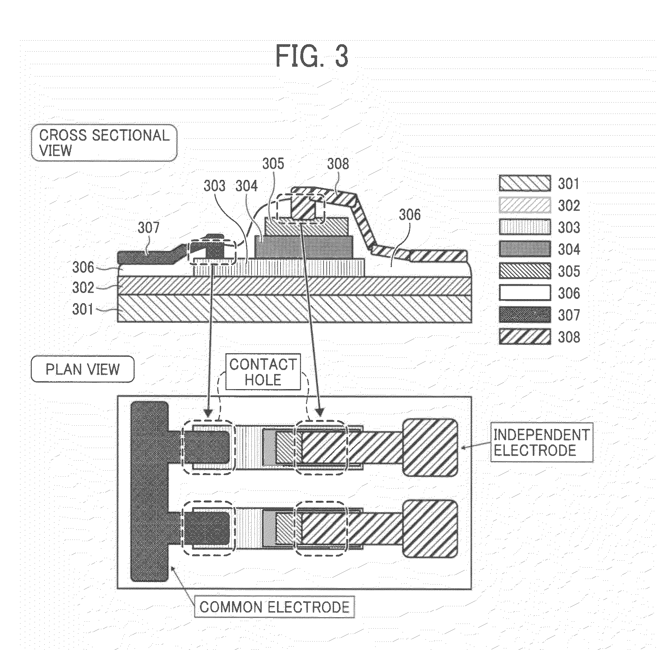
[0148]The process up to the formation of the insulative protection film is performed in a way similar to, if not the same as, the above-described way of Example 1. Then, an Al film of a thickness of, for example, 5 μm is formed as a third electrode and a fourth electrode by sputtering. Further, a photoresist (for example, TSMR8800 manufactured by TOKYO OHKA KOGYO Co., Ltd.) is coated by spin coating and patterned by standard photolithographic processing. A pattern illustrated in FIG. 3 is formed by a reactive ion etching (RIE) apparatus (manufactured by, for example, SAMCO Inc.) so that the third electrode of metal (Al) is formed on the first electrode so as to electrically conduct the first electrode as a common electrode via contact holes and the fourth electrode of metal (Al) is formed on the second electrode so as to electrically conduct the first electrode as an independent electrode via contact holes. Thus, the electro-mechanical transducer of Example 3 is manufactured.


PUM

PropertyMeasurementUnit
thicknessaaaaaaaaaa
thicknessaaaaaaaaaa
thicknessaaaaaaaaaa

Abstract

An electro-mechanical transducer includes a plurality of independent elements. Each of the plurality of independent elements includes one of a substrate and a foundation film, a first electrode of oxide disposed on the one of the substrate and the foundation film, an electro-mechanical transducer film disposed on the first electrode, a second electrode of oxide disposed on the electro-mechanical transducer film, and a third electrode of metal formed on the first electrode as a common electrode conductive to the first electrode and common to at least two of the plurality of independent elements.

Description

CROSS-REFERENCE TO RELATED APPLICATIONS[0001]The present patent application claims priority pursuant to 35 U.S.C. §119 from Japanese Patent Application No. 2009-242170, filed on Oct. 21, 2009 in the Japan Patent Office, which is incorporated herein by reference in its entirety.BACKGROUND OF THE DISCLOSURE[0002]1. Field of the Disclosure[0003]Exemplary embodiments of the present disclosure relate to an electro-mechanical transducer usable as a piezoelectric actuator of an inkjet recording head, a liquid ejection head including the electro-mechanical transducer, and a liquid ejection apparatus including the liquid ejection head.[0004]2. Description of the Background[0005]Image forming apparatuses are used as printers, facsimile machines, copiers, plotters, or multi-functional peripherals having two or more of the foregoing capabilities. As one type of image forming apparatus employing a liquid-ejection recording method, an inkjet recording apparatus is known that uses a recording head...

Claims


Application Information

Patent Timeline
Patent Type & Authority Applications(United States)
IPC IPC(8): B41J2/045H01L41/047H01L41/22B05C5/00B41J2/055B41J2/135B41J2/14B41J2/16H01L41/09H01L41/18H01L41/187H01L41/23H01L41/29H01L41/331
CPCH01L41/1876H01L41/0973H01L41/318B41J2/1631B41J2/1642H01L41/29Y10T29/42B41J2/1646B41J2/1645B41J2/1629B41J2/161H01L41/0477B41J2/1628H10N30/877H10N30/2047H10N30/8554H10N30/06H10N30/078B41J2/045
Inventor MIZUKAMI, SATOSHI
Owner RICOH KK
Why Eureka
Try Eureka