Contactless power receiver and method of operation

a power receiver and contactless technology, applied in power conversion systems, electrical equipment, circuit arrangements, etc., can solve the problems of large conduction loss, low efficiency when light-loading, frequency variation,

Inactive Publication Date: 2011-04-21
APPLE INC
View PDF28 Cites 65 Cited by
  • Summary
  • Abstract
  • Description
  • Claims
  • Application Information

AI Technical Summary

Benefits of technology

[0046]While the present invention has been illustrated by the description of the embodiments thereof, and while the embodiments have been described in detail, it is not intended to restrict or in any way limit the scope of the appended claims to such detail. Additional advantages and modifications will readily appear to those skilled in the art. Therefore, the invention in its broader aspects is not limited to the specific details, representative apparatus and method, and illustrative examples shown and described. Accordingly, departures may be made from such details without departure from the spirit or scope of the general inventive concept.

Problems solved by technology

One of the issues with contactless power receivers is their low efficiency when they are lightly loaded, for example when a motor powered by a power receiver is idle while it awaits a command from a control system.
Although the technology addresses the power flow control problem from the pickup to the load, the shorting switch can cause large conduction losses, especially at light loads because the pickup circuit is nearly always shorted under no load or light load conditions.
Another problem with contactless power systems is frequency variations due to changes in load conditions and other circuit parameters.
This can cause changes in the pick-up coil in terms of the induced voltage magnitude and short circuit current, which affect the power transfer capacity of the system.
This is particularly a problem in fixed or passively tuned contactless power receivers.
This implementation causes excessively high currents or voltages because either the inductor current can be switched off or the capacitor can be shorted during the switching process.
The resulting switching transients contribute to EMI, stresses of tuning semiconductor switches, and reduces the system power efficiency due to excessive power losses.
In the worst cases it can cause system failure.

Method used


Image

  • Contactless power receiver and method of operation
  • Contactless power receiver and method of operation
  • Contactless power receiver and method of operation

Examples


Embodiment Construction

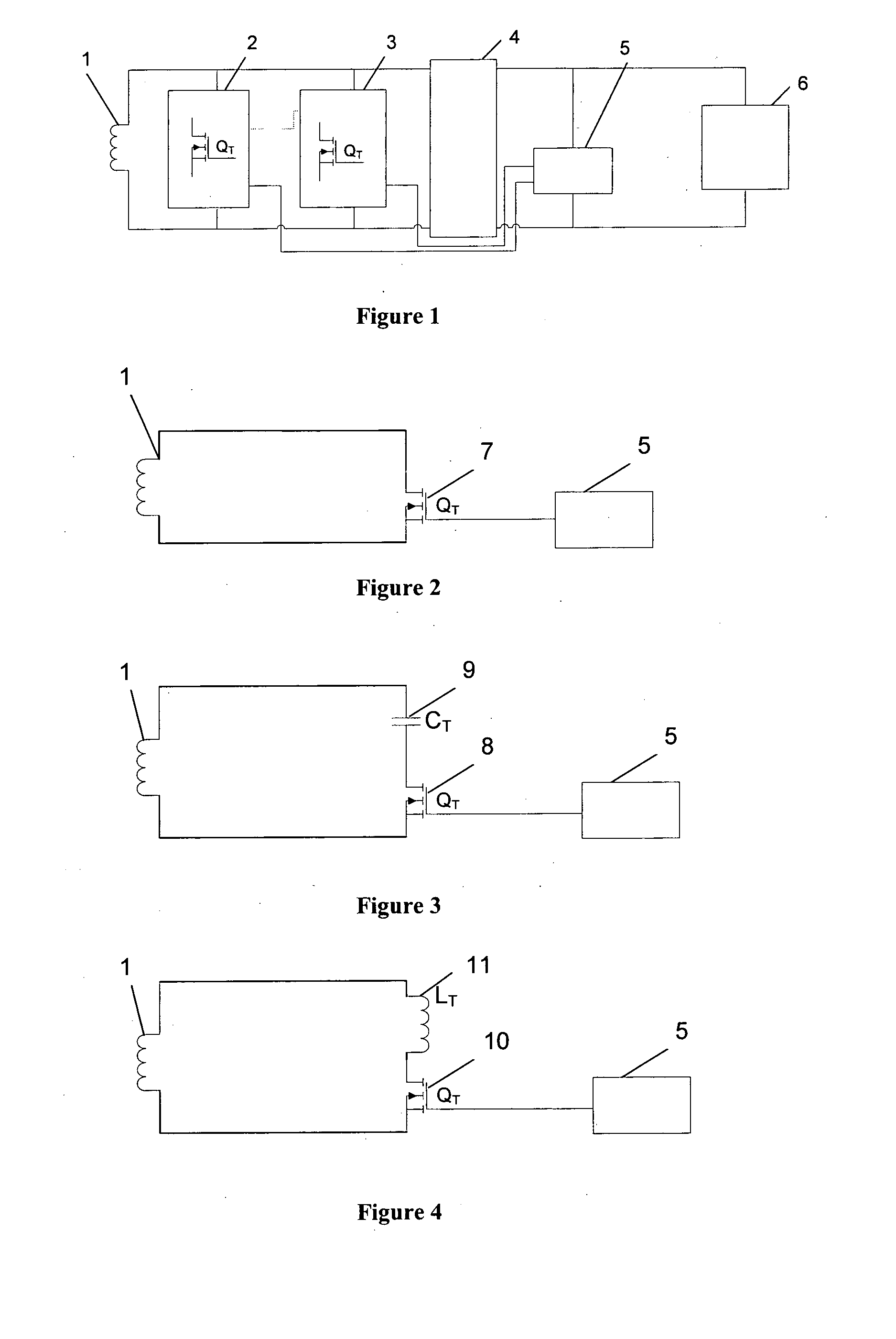
[0022]FIG. 1 shows a contactless power receiver that includes a pick up coil 1 that is connected to one or more semiconductor switches 2, 3. These semiconductor switches 2, 3 are driven by a control circuit 5 that modulates the semiconductor switches 2, 3. The design also includes a full or half bridge rectifier circuit 4 to provide a DC supply for the control circuit 5 and the electronic or energy storage device 6.

[0023]When in proximity of a magnetic field an electromotive force is induced in pick up coil 1. As the magnetic coupling between the magnetic field and pick up coil 1 is very loose compared to traditional transformers, the induced voltage is usually unsuitable for direct use.

[0024]A power controller is necessary to regulate the power depending on the power requirements of the electronic or energy storage device 6. The pick up coil 1 also needs to be tuned in order to increase the power transfer capacity of the system. A dynamic tuning method can be used to regulate the p...


PUM


Abstract

A contactless power receiver is provided with a dynamically tuned pick up coil. The power transfer capacity of this power receiver is dynamically tuned using semiconductor devices that are operated in linear mode over part of their operation. The semiconductor devices are driven by a controller that is configured to implement a range of control strategies depending on system requirements. The semiconductor device may be used by itself or in conjunction with reactive elements to dynamically tune the pick up coil. In some implementations the contactless power receiver maybe configured to work with a consumer electronic or a wireless sensor device. The contactless power receiver can be integrated with the energy storage component of the device to provide a retrofit solution for existing products. The device can then be placed in vicinity of a planar magnetic field generated by a charging pad.

Description

FIELD OF THE INVENTION[0001]The present invention is in the technical field of Inductively Coupled Power Transfer systems (ICPT). More particularly the present invention relates to a contactless power receiver including a semiconductor switch operating in linear mode.BACKGROUND OF THE INVENTION[0002]Contactless power systems comprise of a contactless power transmitter that includes a conductive path supplied with alternating current from a power supply and one or more contactless power receivers. These contactless power receivers are within proximity, but electrically isolated from, the conductive path. A contactless power receiver includes a pick up coil in which a voltage is induced by the magnetic field generated by the conductive path, and supplies an electric load. The pick up coil is usually tuned using a tuning capacitor to increase power transfer capacity of the system.[0003]One of the issues with contactless power receivers is their low efficiency when they are lightly load...

Claims


Application Information

Patent Timeline
Patent Type & Authority Applications(United States)
IPC IPC(8): H02M7/155
CPCH02J5/005H02J50/12H02J50/10
Inventor HU, PATRICK AIGUOSI, PINGBHARGAVA, KUNALMISHRIKI, FADY
Owner APPLE INC
Why Eureka
Try Eureka