System and Method for Image Reconstruction by Using Multi-Sheet Surface Rebinning

a surface rebinning and multi-sheet technology, applied in the field of image reconstruction, can solve the problems of poor image reconstruction, simple two-dimensional inverse radon transform cannot be used to reconstruct an image on that plane, and the rate at which tomographic images can be acquired by such systems, so as to improve the approximation

Active Publication Date: 2011-04-21
RAPISCAN SYST INC (US)
View PDF20 Cites 13 Cited by
  • Summary
  • Abstract
  • Description
  • Claims
  • Application Information

AI Technical Summary

Benefits of technology

[0029]The method uses said set of simultaneous equations incorporating the direction point spread functions in an axial direction to improve approximation with detected X-rays which were at least partially not on a rebinning surface. The method includes the steps of performing backprojection without filtering on multi-sheet surfaces; axial deconvolution; and subsequently filtering on each transaxial s

Problems solved by technology

The rate at which tomographic images can be acquired by such systems is limited by the rate of rotation of the assembly supporting the source and detector array.
Hence, a simple two dimensional inverse Radon transform cannot be used

Method used


Image

  • System and Method for Image Reconstruction by Using Multi-Sheet Surface Rebinning
  • System and Method for Image Reconstruction by Using Multi-Sheet Surface Rebinning
  • System and Method for Image Reconstruction by Using Multi-Sheet Surface Rebinning

Examples


Embodiment Construction

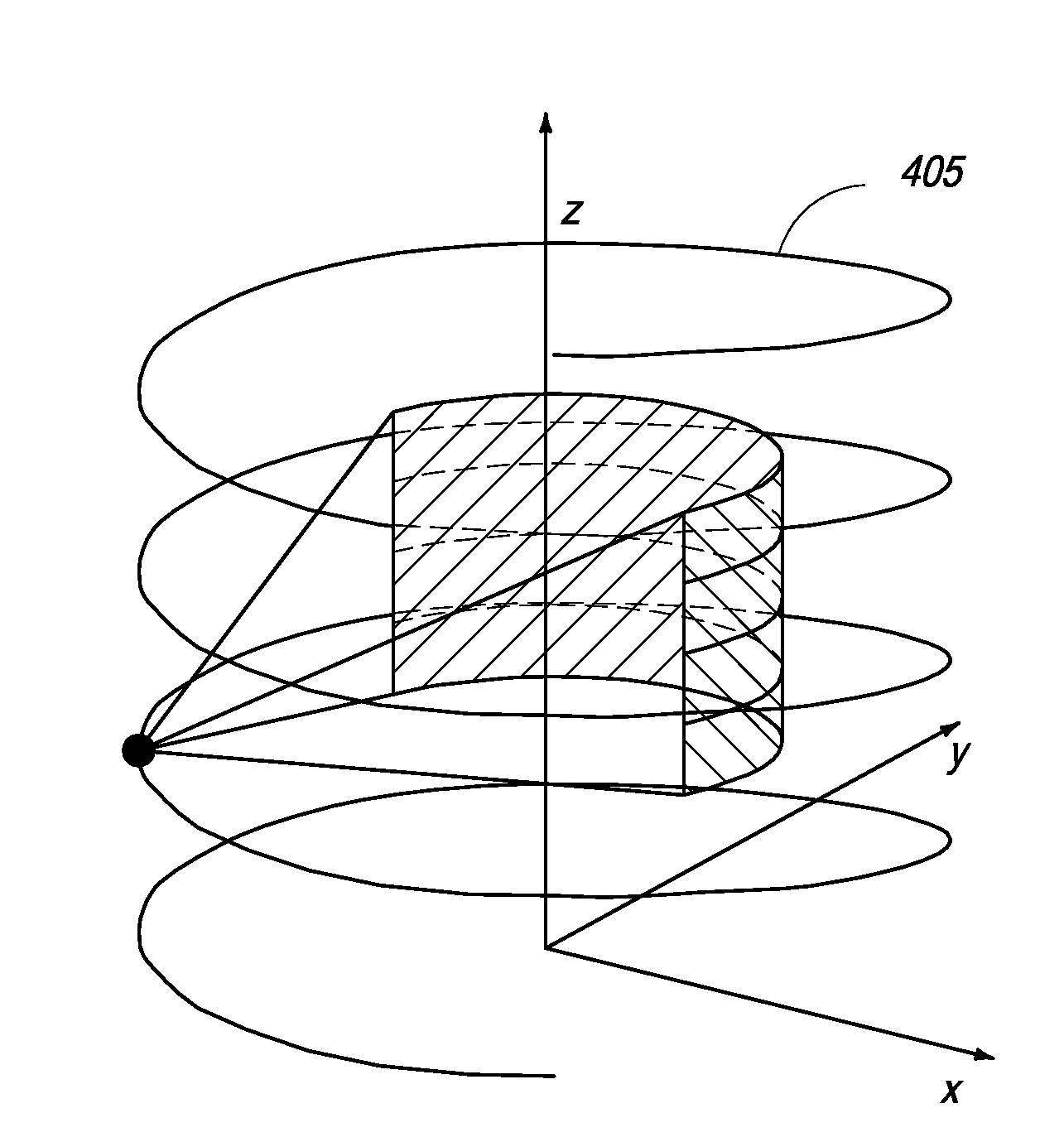
[0037]The present invention provides a method of reconstructing images from a cone beam tomographic sensor in which detectors are not located directly opposite radiation sources. In one embodiment, the present invention applies to X-ray computerized tomography. More generally, the present invention applies to methods of image reconstruction, wherein, radiation is assumed to propagate along straight lines through an attenuating medium. In an embodiment, the method of the present invention may be applied to image reconstruction in systems using gamma rays. The method of reconstructing images uses data from rays close to a multi-sheet surface which may have a conical singularity where the sheets of the surface meet or the sheets may cross along contours. This data is reconstructed in a manner similar to reconstruction of data from rays in a plane, by using a two dimensional reconstruction algorithm on a plurality of sheets. The volumetric image is recovered by solving a system of simul...


PUM


Abstract

The present application is directed toward the generation of three dimensional images in a tomography system having X-ray sources offset from detectors, in particular in a system where the sources are located on a plane, while detectors are located on multiple parallel planes, parallel to the plane of sources and all the planes of detectors lie on one side of the plane of sources. A controller operates to rebin detected X-rays onto a non-flat surface, perform two dimensional reconstruction on the surface, and generate the three dimensional image from reconstructed images on the plurality of surfaces.

Description

CROSS REFERENCE[0001]The present invention relies on U.S. Provisional Patent Application No. 61 / 225,257, of the same title, and filed on Jul. 14, 2009, for priority.[0002]The present application is also a continuation-in-part of U.S. patent application Ser. No. 12 / 485,897, filed on Jun. 16, 2009, which is a continuation of U.S. patent application Ser. No. 10 / 554,656, filed on Oct. 25, 2005, and now issued U.S. Pat. No. 7,564,939, which is a 371 national stage application of PCT / GB04 / 01729, filed on Apr. 23, 2004 and which, in turn, relies on Great Britain Application No. 0309387.9, filed on Apr. 25, 2003, for priority.[0003]The present application is also a continuation-in-part of U.S. patent application Ser. No. 12 / 371,853, filed on Feb. 16, 2009, which is a continuation of U.S. patent application Ser. No. 10 / 554,975, filed on Oct. 25, 2005, and now issued U.S. Pat. No. 7,512,215, which is a 371 national stage application of PCT / GB2004 / 01741, filed on Apr. 23, 2004 and which, in tu...

Claims


Application Information

Patent Timeline
IPC IPC(8): A61B6/03
CPCA61B6/032A61B6/4014A61B6/5205G01N2223/419G06T11/005A61B6/027G01N23/046
Inventor BETCKE, MARTALIONHEART, WILLIAM ROBERT BRECKONMORTON, EDWARD JAMES
Owner RAPISCAN SYST INC (US)
Why Eureka
Try Eureka