Fuel cell and fuel cell stack

a fuel cell and stack technology, applied in the field of fuel cell and fuel cell stack, can solve the problems of increasing the size and weight of the fuel cell system, and achieve the effects of reducing weight, improving power generation efficiency, and efficiently exhausting reaction products

Inactive Publication Date: 2011-04-21
SHARP KK
View PDF3 Cites 31 Cited by
  • Summary
  • Abstract
  • Description
  • Claims
  • Application Information

AI Technical Summary

Benefits of technology

[0018]A fuel cell according to the present invention can be smaller, thinner, and reduced in weight, and can exhaust a reaction product efficiently. Also, power generation efficiency is improved therein. Such a fuel cell according to the present invention can be suitably used as a unit constituting a fuel

Problems solved by technology

This results in, however, increased size and we

Method used


Image

  • Fuel cell and fuel cell stack
  • Fuel cell and fuel cell stack
  • Fuel cell and fuel cell stack

Examples


first embodiment

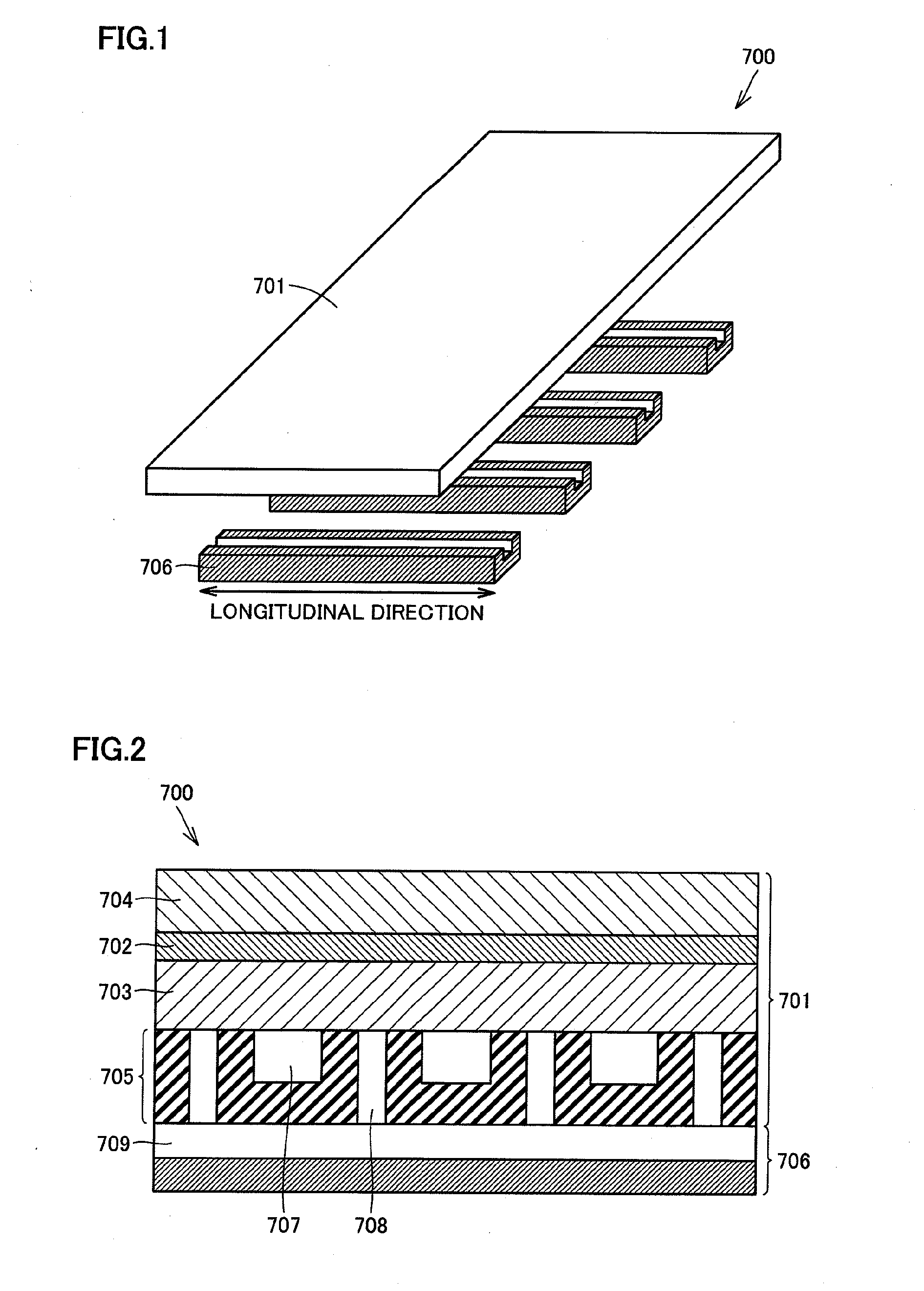
[0030]FIG. 1 and FIG. 2 are an exploded perspective view and a cross sectional view, each of which schematically shows a preferred exemplary fuel cell of the present invention. A unit cell 701, which constitutes a fuel cell 700 shown in FIG. 1 and FIG. 2, includes an electrolyte membrane 702, an anode electrode 703 disposed on one surface of electrolyte membrane 702, a cathode electrode 704 disposed on the other surface of electrolyte membrane 702, and an anode collector layer 705 disposed in contact with an opposite surface of anode electrode 703 to the electrolyte membrane 702 side. Fuel cell 700 is constituted by unit cell 701 and one or more spacers 706 arranged on anode collector layer 705. The term “unit cell” herein refers to one unit constituting a fuel cell, and is defined as a structure including a membrane electrode assembly (MEA) and optionally other components combined with the membrane electrode assembly for the purpose of providing a power generation function or other...

second embodiment

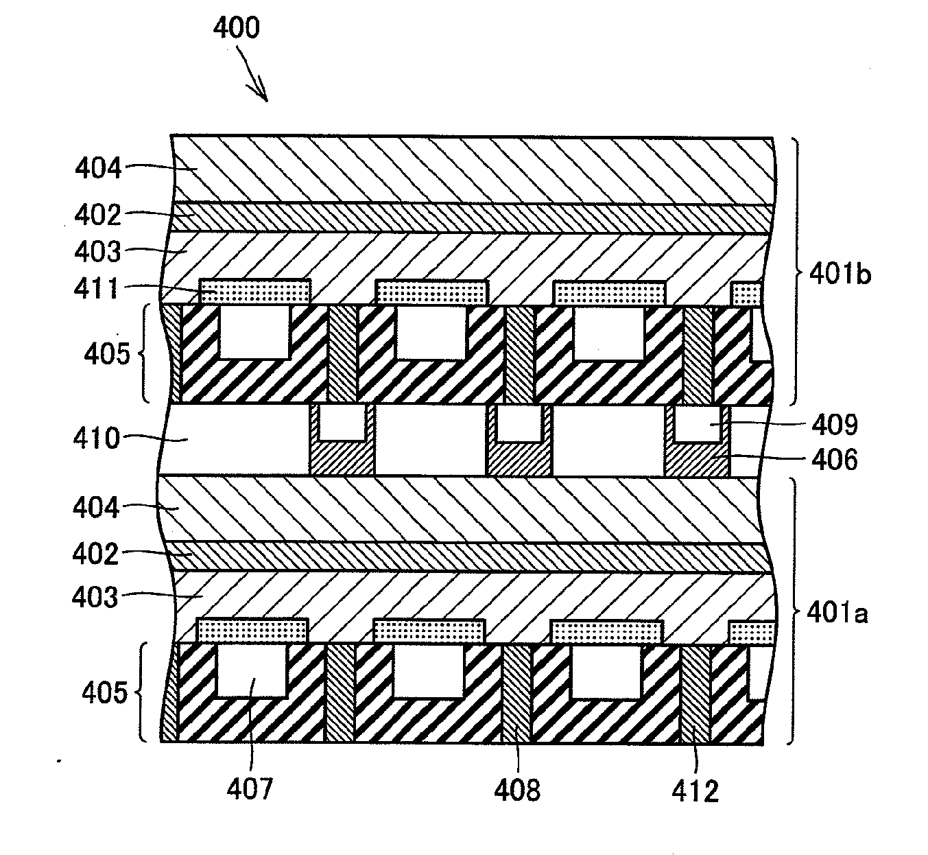
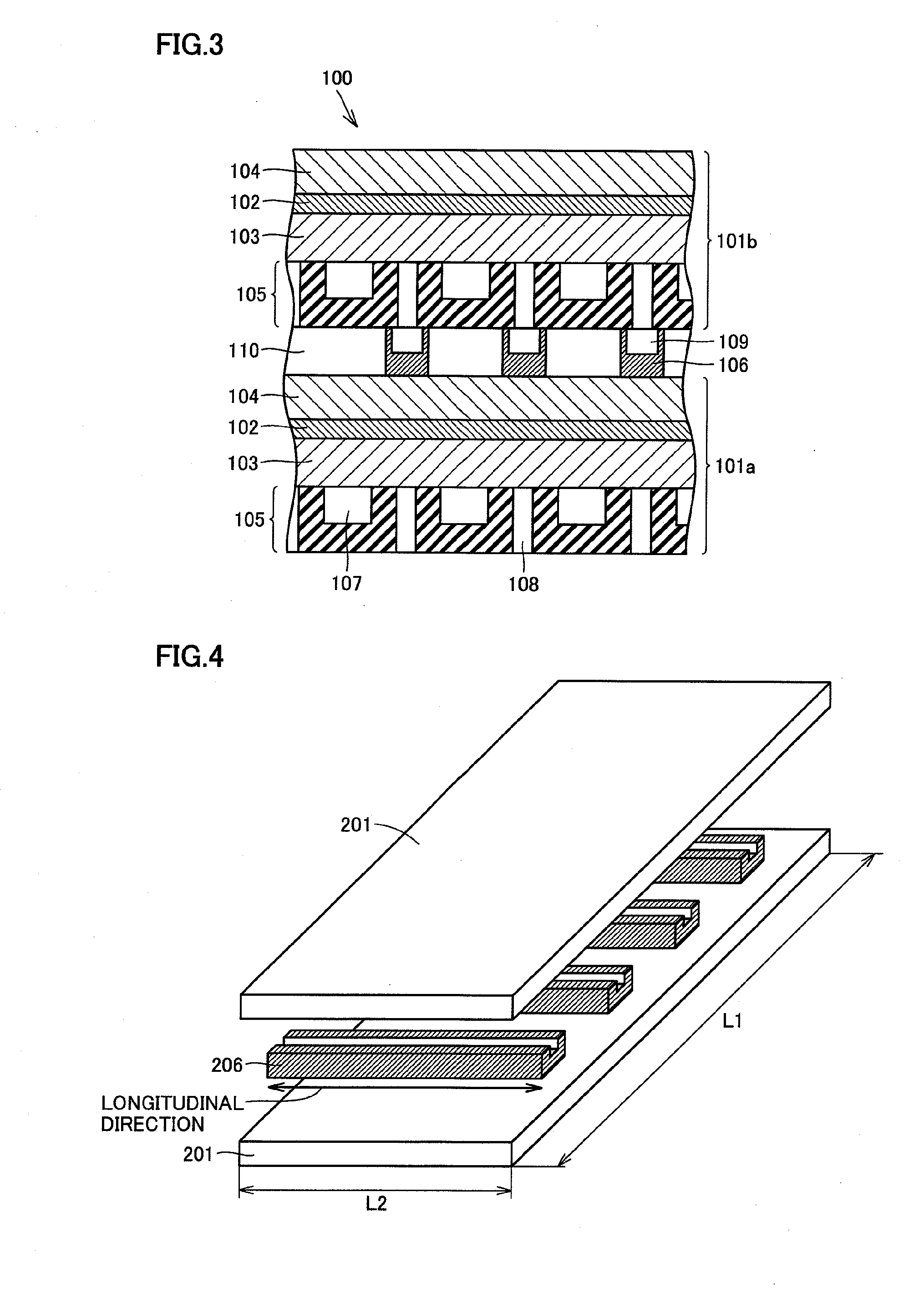
[0033]FIG. 3 is a cross sectional view schematically showing a preferred exemplary fuel cell stack of the present invention. A fuel cell stack 100 shown in FIG. 3 includes a first unit cell 101a and a second unit cell 101b, each of which includes an electrolyte membrane 102, an anode electrode 103 disposed on one surface of electrolyte membrane 102, a cathode electrode 104 disposed on the other surface of electrolyte membrane 102, and an anode collector layer 105 disposed in contact with an opposite surface of anode electrode 103 to the electrolyte membrane 102 side. Fuel cell stack 100 is formed by arranging first unit cell 101a and second unit cell 101b with one or more spacers 106 interposed therebetween so that cathode electrode 104 of first unit cell 101a faces anode collector layer 105 of second unit cell 101b.

[0034]Anode collector layer 105 includes fuel flow paths 107 each of which is a space for transportation of fuel, and through holes 108 for exhausting a reaction produc...

third embodiment

[0077]FIG. 5 is a cross sectional view schematically showing another preferred exemplary fuel cell stack of the present invention. A fuel cell stack 300 shown in FIG. 5 has a configuration similar to that of the foregoing second embodiment, except that fuel permeation layers 311 are provided. The following describes the fuel permeation layer in detail.

[0078]

[0079]Fuel permeation layer 311 is a layer allowing the fuel to pass therethrough, has a diffusion resistance of the fuel in the thickness direction thereof, and has a function of restricting a permeation flux of the fuel. Further, fuel permeation layer 311 is not porous and has a function of blocking permeation of the gas in the thickness direction thereof. As shown in FIG. 5, fuel permeation layer 311 is formed between an anode collector layer 305 and an anode electrode 303 so as to cover an opening at the anode electrode 303 side of a fuel flow path 307.

[0080]Fuel permeation layer 311 thus provided with such a configuration al...


PUM


Abstract

The present invention relates to a small fuel cell and a small fuel cell stack each allowing for improved output. Conventionally, in a direct methanol fuel cell, carbon dioxide gas produced at an anode electrode side is exhausted together with a methanol aqueous solution. From the methanol aqueous solution, the carbon dioxide gas is separated, and then the methanol aqueous solution is reused as fuel. In this case, a liquid-gas separation device needs to be provided additionally, which results in a large fuel cell with an increased weight, disadvantageously. The present invention is made to solve such a problem by providing a fuel cell including a first unit cell having a cathode electrode, an electrolyte membrane, an anode electrode, and an anode collector layer in this order; and one or more spacers arranged on the anode collector layer. The anode collector layer has a fuel flow path for supplying fuel to the anode electrode, and a through hole for exhausting a reaction product generated by reaction in the anode electrode. Each of the spacers has an exhaust flow path for exhausting the reaction product to outside the fuel cell. The through hole and the exhaust flow path communicate with each other.

Description

TECHNICAL FIELD[0001]The present invention relates to a fuel cell and a fuel cell stack allowing for downsizing and improved output.BACKGROUND ART[0002]In recent years, expectations for fuel cells are increasing as small power sources for portable electronic devices used in the information society because they have a potential of achieving high power generation efficiency as an individual power generating device. The fuel cell is a chemical cell that utilizes electrochemical reaction to supply electrons to a portable electronic device or the like. The electrochemical reaction involves oxidizing a fuel (such as hydrogen, methanol, ethanol, hydrazine, formalin, or formic acid) at the anode and reducing oxygen in air at the cathode.[0003]Of such a wide variety of fuel cells, a polymer electrolyte membrane fuel cell (hereinafter, abbreviated as “PEMFC”), which employs a proton-exchanged, ion-exchanged membrane as an electrolyte membrane, will be likely to be put into practical use as a ...

Claims


Application Information

Patent Timeline
IPC IPC(8): H01M8/06H01M8/24
CPCH01M8/0247H01M8/026H01M8/1011Y02E60/523H01M2250/30Y02B90/18H01M2008/1095Y02B90/10Y02E60/50
Inventor KAMBARA, HIRONORIFUJITA, TOSHIYUKIYOSHIE, TOMOHISATSUKUDA, YOSHIHIROKOGURE, CHIKAAKISATA, SHUNSUKE
Owner SHARP KK
Why Eureka
Try Eureka