
Ostomy appliances for effluent control

a technology for effluent control and ostomy, which is applied in the field of ostomy appliances for effluent control, can solve the problems of weight gain, difficult management of flushing and recessed stomas, and inability to properly form stomas, etc., and achieves the effects of convenient insertion, convenient insertion, and sufficient tim

Active Publication Date: 2011-04-21
CONVATEC TECH INC
View PDF6 Cites 42 Cited by
  • Summary
  • Abstract
  • Description
  • Claims
  • Application Information

AI Technical Summary

Benefits of technology

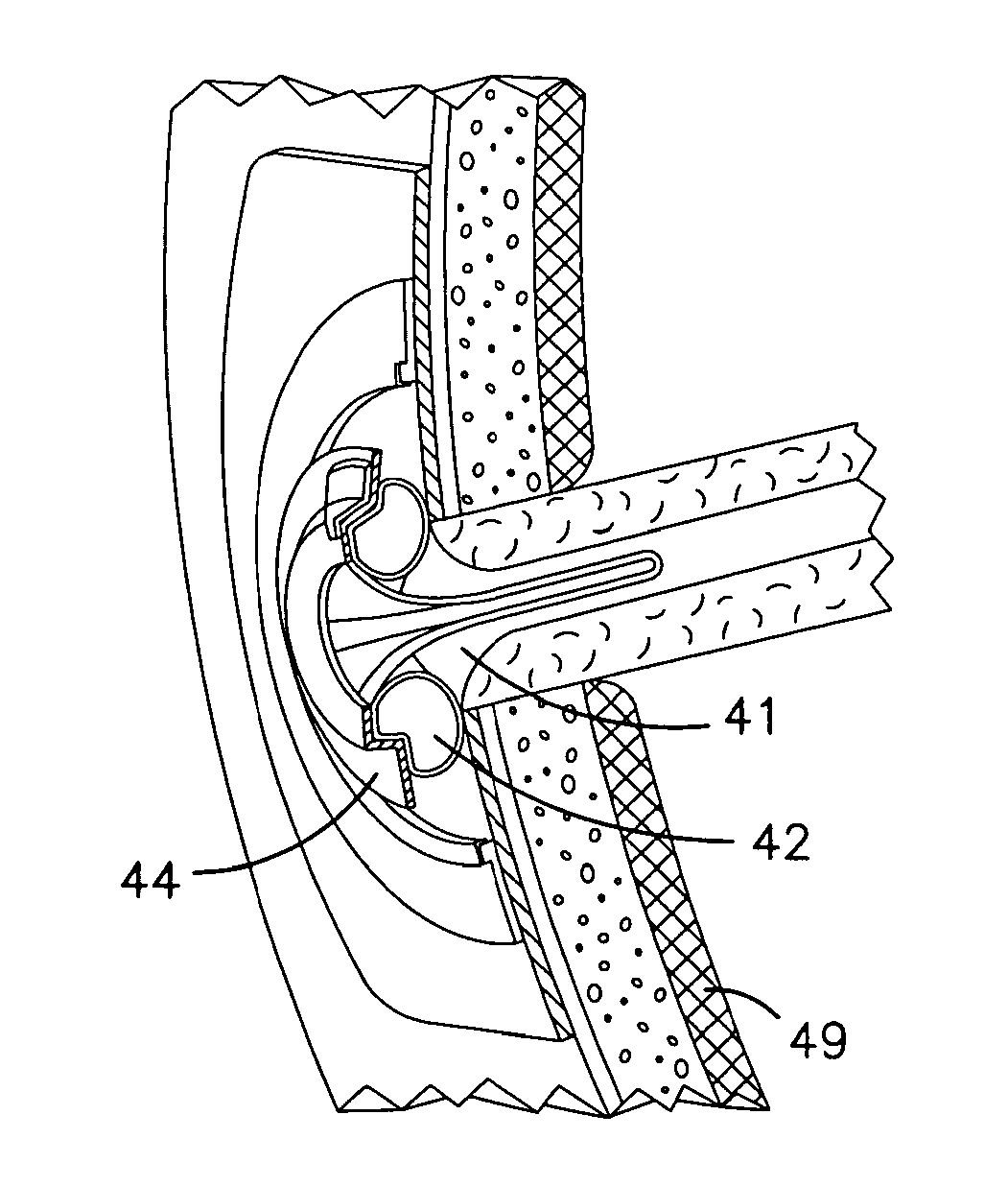
[0020](g) The seal comprising the internally inflated chamber portion may be constructed of a single chamber or dual interconnecting chambers attached and / or bonded to, or constructed of one formed shape, with a tubular, more firm or rigid central member. The proximal end of this assembly or component may be attached to another more elastic tubular member, or the central member itself continues outside the body, so as to provide a passageway through the device. With embodiments having the other more elastic tubular member, the shape may be tubular straight, tapered or “trumpet-like”. The assembly / component comprising the single or dual chambers, and the more firm central tubular member, are to be inserted fully behind the fascia and inflated, while the proximal end of the central member or the more elastic straight, tapered or “trumpet” shaped tubular member remains external to the stoma. This assembly configuration may allow for easy insertion into the stoma opening without the need for an insertion device.
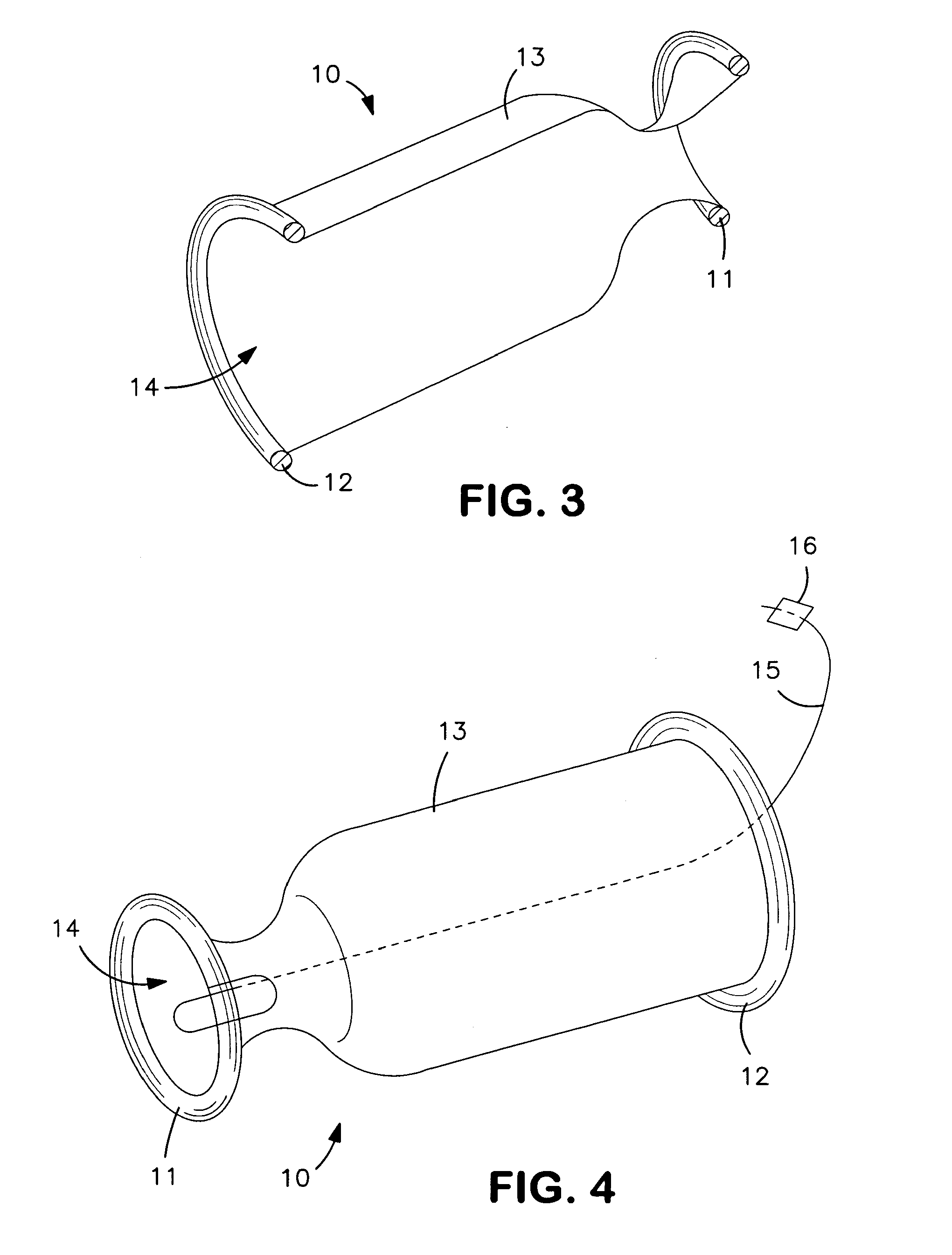
[0022](i) The member comprising the seal external to the stoma may not only be constructed of a thicker toroidal-shaped elastic material or O-ring for a manual circumferential detent adjustment to the fascia-skin distance, but may also contain a pressurized chamber, i.e., an inflatable O-ring. This chamber is to be pressurized with fluid at manufacture or at some time previous to use, such that the pressure contained, when released, can be utilized to transfer, via elastic action, the fluidic component through interconnecting passageways into the internal chamber so the internal chamber may be deployed while within the body, thereby eliminating the need of a secondary component for inflating the device. An orifice or other fluid restriction, or valve may be used at the entrance, exit or along the interconnecting passageways to delay device deployment to allow the user sufficient time for device insertion. The internal chamber may be constrained, e.g., folded, rolled and / or twisted, into a thin, long shape to ease insertion into the stoma prior to device deployment without the need for an insertion tool. Gelatine or other coating on the constrained internal chamber may facilitate insertion by maintaining the constraint until the gelatine contacts or is within the moist interior of the stoma. The addition of a cap over the internal chamber may also aid in maintaining the chamber in a constrained condition before use.
[0023](j) The member external to the stoma may not comprise an external seal but may only rest or attach and have “vents” allowing fluid escape in the event the internal seal to the intestine is compromised. The effluent venting may prevent occlusion of the stoma opening in the event of seal failure. The effluent venting may also be an indicator that the device is in need of replacement.
[0024](k) The member external to the stoma, with embodiments that have amore firm central tubular member, may be comprised of a more rigid material, effectively a collar, and may possesses features along the contacting surface with the central member such that the collar may be manually placed over and easily slid down the central member but will meet more resistance moving up the central member. This may be accomplished via angled, bendable protrusions with sharp ends extending radially inward and contacting the central member so that movement in one direction (downward or distally) is facilitated but opposite movement (upward or proximally) is restrained. The restrained movement in the proximal direction of the collar may not be full but measured so as to prevent tissue damage in the event of excessive or unexpected body movement. Another embodiment may involve a locking feature within the collar whereas once the collar is in place over the central tubular member a second component of the collar interacts to squeeze the central tubular member sufficiently so as to hold the collar in its position on the member.
[0025](l) Successfully packaging the device embodiments possessing the pressurized external chamber or inflatable O-ring (ref. ‘i’ above) may be accomplished by utilizing a container pressurized with the same fluid and to the same pressure as the device in the non-deployed state. This may alleviate the problem of the device depressurizing over time due to the permeability of the device materials. The package container may be constructed of barrier films or may be a hard polymer or an aluminum (e.g., like a soda can) or other container that will hold the fluidic pressure over time until the contained device is needed.
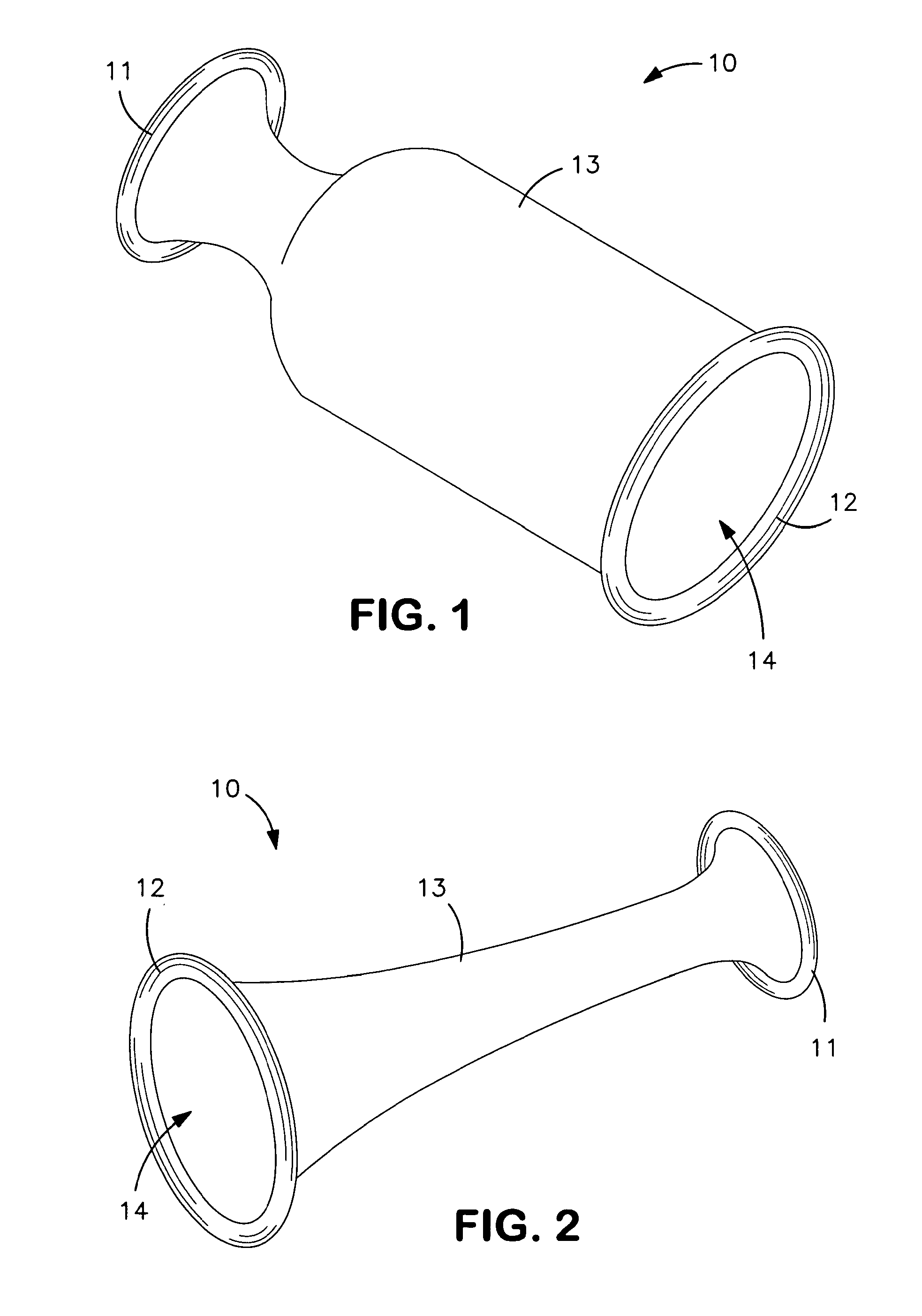
[0028]Features and advantages of the invention may include: providing an ostomy seal that is comfortable and effective without creating high concentrations of pressure internally or externally, and which can produce a comfortable peristomal seal; the ability to adjust to the varying fascia-skin distances and provide an elastic range to accommodate movement; the means of insertion and removal from the stoma; and the feature of “self-inflation” by means of internally containing the fluidic pressure to actuate and / or deploy the device.

Problems solved by technology

Irritation can result if the peristomal tissue is exposed to body waste, or to repeated application and removal of adhesive or other sealants.
These can include improper formation of the stoma by the surgeon; and post-operative weight gain by the ostomate.
Flush and recessed stomas can be difficult to manage, because some effluent discharged from the stoma can tend to pool around the stoma, instead of the effluent discharging completely into the pouch.
Such attack reduces the adhesion of the body fitment to the skin, thereby reducing the effectiveness and the usable life of the appliance.
The stool can also cause irritation and degradation of the peristomal skin itself.
Stool exiting the stoma may contain digestive juices from the body, and such juices can attack the peristomal skin resulting in excoriation.
It is hitherto not known for a single device to accommodate varying distances between the stoma and skin level.
However, such devices have to be designed carefully to avoid the risk of damage to the sensitive internal tissue.
In such designs, a relatively high concentration of force may be placed on the tissue underneath the stoma, effecting blood circulation in the area under pressure, thereby over time leading to tissue necrosis.
Additionally, the device has very little or no range of adjustment to the varying distance between the underside of the fascia and the skin, limiting the use to individuals whose fascia-skin distance is within the range of the device.
To have the user carry around an extra component is inconvenient, and the inflation mechanism may not have a means to control the amount of fluid to be pumped into the device, which brings associated risks of under or over-inflation of the device.
The peristomal tissue is either unprotected or is protected by the adhesive wafer, leaving the possibility that the peristomal tissue may be vulnerable to the conventional problem of irritation and pain resulting from exposure to stool or repeated applications and removals of adhesive.

Method used


Image

  • Ostomy appliances for effluent control
  • Ostomy appliances for effluent control
  • Ostomy appliances for effluent control

Examples


first embodiment

[0060]In another embodiment the shape of the elastic covering 21, which forms the central channel 14 may also be of a tubular tapered shape attached to an external O-ring 12 as in the first embodiment above (FIGS. 1, 3 and 4).

[0061]Still another embodiment may have the supporting ringed feature 19 extend in a tubular straight shape through the stoma passageway and out of the body.

[0062]The means of inserting the ostomy appliance 10 into the stoma may involve the use of a tubular shaped insertion tool (not shown). The tool is placed through the central channel 14 from the proximal end of the ostomy appliance 10, passes through the ringed feature 19, and the tool end engages the curved ends of the protrusions 17 when they are bent together into a cylindrical shape. The tool may be held in place by adhesive and / or engaging features at the tool end. The protrusions 17 may also possess adhesive and / or engaging features. The tool may also be held in place via a feature that maintains a fi...

fourth embodiment

[0065]In the ostomy appliance 10, referring to FIG. 6, an ostomy appliance 10 may include a seal for sealing around a stoma such that the seal comprising the internal portion for sealing against the internal wall of the stoma lumen consists of an expandable foam material 22. This foam material 22 covers the exterior of a more rigid central support 23 that is of a generally tubular shape, but having a semi-spherical bulge 24 at the distal end and flange-like feature 25 at the proximal end. The foam material 22 may have varying thicknesses over different portions of the central support 23, e.g., it may be thicker over the semi-spherical bulge 24. The foam material 22 expands significantly in the presence of moisture. Over the exterior of the foam material 22 may be a coating or covering of very thin, elastic sealing film 27. The flange-like feature 25 remains exterior to the body when the ostomy appliance 10 is in place so as to be clear of the stoma, and may attach to the skin, an ex...

fifth embodiment

[0069]The inflated chamber portion 28 of the ostomy appliance 10 is inserted fully behind the fascia. The proximal end of the ostomy appliance 10, which includes a portion of the elastic tubular member 31 and the attached O-ring 12, remains external to the stoma. The dual interconnecting chambers 29 are then inflated via an inflation tube 32 that has a check valve, and an inflation device such as a syringe. Once inflated, as with previous embodiments, the external O-ring 12 is then grasped and gently tugged outward to seat the most proximal of the dual interconnecting chambers 29 against the fascia. The external O-ring 12 is then manually rolled so as to adjust to the specific distance between the fascia and skin. The firmness of the external O-ring 12 acts to maintain the position of the rolled up length and the elastic rebound of the tubular member 31 provides an elastic range to accommodate body movement when the ostomy appliance 10 is worn. Also, as with previous embodiments, th...


PUM


Abstract

A stoma extender includes a first end for insertion into a stoma for diverting stomal effluent into the stoma extender before the effluent exits the stoma; a second end for remaining external of the stoma, for providing a discharge exit for stomal effluent; and a conduit portion coupled between the first and second ends for communicating stomal effluent through the stoma extender, wherein the length of the conduit portion is adjustable stably, to permit adaptation of the stoma extender to an individual's stoma.

Description

[0001]The present invention relates to the field of ostomy appliances for fitting and sealing within and around an ostomate's stoma to direct effluent output. Other aspects of the invention relate to the ability to adjust to the varying distance between the fascia and the skin and the ability to “self-inflate” via fluidic actuation. The term “ostomy” is intended to cover at least colostomy, ileostomy and urostomy.BACKGROUND TO THE INVENTION[0002]Effectively directing or otherwise controlling effluent output is central to ostomy devices designed to protect skin adjacent to the discharge area. Creating a seal around a person's stoma, such that the seal is dependable, comfortable and conducive to body tissue, is important for the function of ostomy appliances. Once this seal has been made, the appliance may use one or more of a variety of techniques for managing stomal discharge. The formation of such a seal remains an area of continuous improvement and development, since the performan...

Claims


Application Information

Patent Timeline
IPC IPC(8): A61F5/445
CPCA61F2005/4455A61F5/445
Inventor WEIG, BRET
Owner CONVATEC TECH INC
Learn More