Retrofit Method for Pulverized Coal Boiler

a technology of pulverized coal and boiler, which is applied in the direction of manufacturing tools, lighting and heating equipment, combustion types, etc., can solve the problems of affecting the efficiency of the furnace, and affecting the efficiency of the furnace, and achieves the effect of short time and low cos

Active Publication Date: 2011-04-28
MITSUBISHI POWER LTD
View PDF2 Cites 17 Cited by
  • Summary
  • Abstract
  • Description
  • Claims
  • Application Information

AI Technical Summary

Benefits of technology

In this oxyfuel combustion boiler system, a reduction in the recirculation amount of the exhaust gas helps to avoid a loss in exhaust heat recovery and to reduce the power of a blower for blowing the recirculation gas; thus, it is advantageous in improving net thermal efficiency.
It is an object of the present invention to provide a method for retrofitting a pulverized coal boiler in which, when a pulverized coal boiler in the air combustion system is retrofitted into a two-stage combustion pulverized coal boiler having a burner and an after-air port in the oxyfuel combustion boiler system, the heat load on a furnace wall of the pulverized coal boiler is reduced so that retrofit into a pulverized coal boiler in the oxyfuel combustion boiler system which maintains structural reliability can be achieved at low cost in a short period of time.
According to the present invention, when retrofits a pulverized coal boiler in the air combustion boiler system into a two-stage combustion pulverized coal boiler having a burner and an after-air port in the oxyfuel combustion boiler system, the heat load on a furnace wall of the pulverized coal boiler can be reduced so that retrofit into the pulverized coal boiler in the oxyfuel combustion boiler system which maintains structural reliability can be achieved at low cost in a short period of time.

Problems solved by technology

As a result, the heat load on the furnace is drastically increased, which may damage the furnace due to temperatures exceeding the allowable temperature of metallic material making up the furnace.
This will be a problem.

Method used


Image

  • Retrofit Method for Pulverized Coal Boiler
  • Retrofit Method for Pulverized Coal Boiler
  • Retrofit Method for Pulverized Coal Boiler

Examples


embodiment 1

The method for retrofitting a pulverized coal boiler in an air combustion boiler system into a pulverized coal boiler in an oxyfuel combustion boiler system according to an embodiment of the present invention will be described.

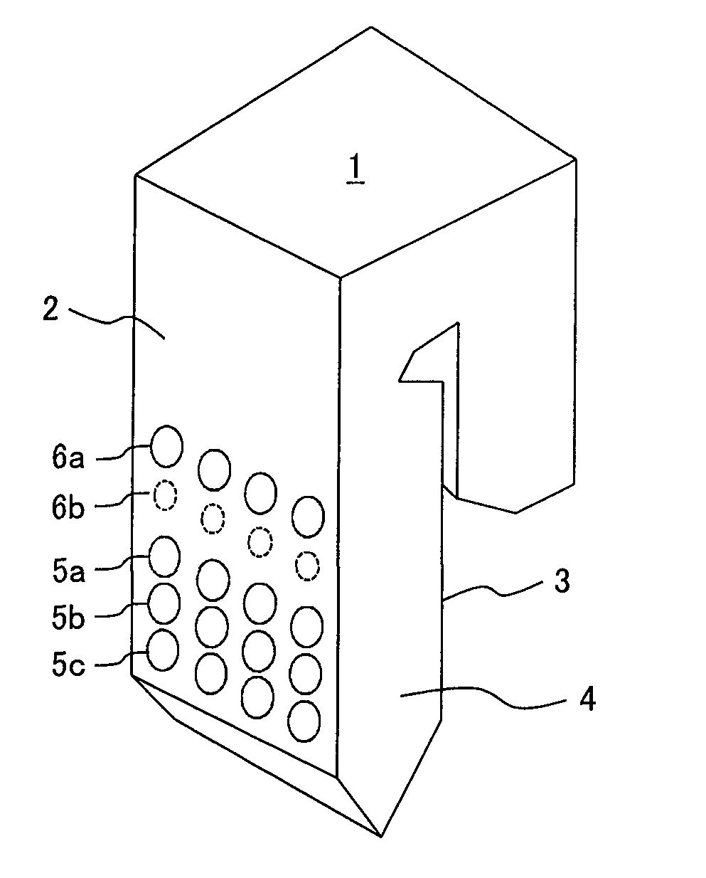
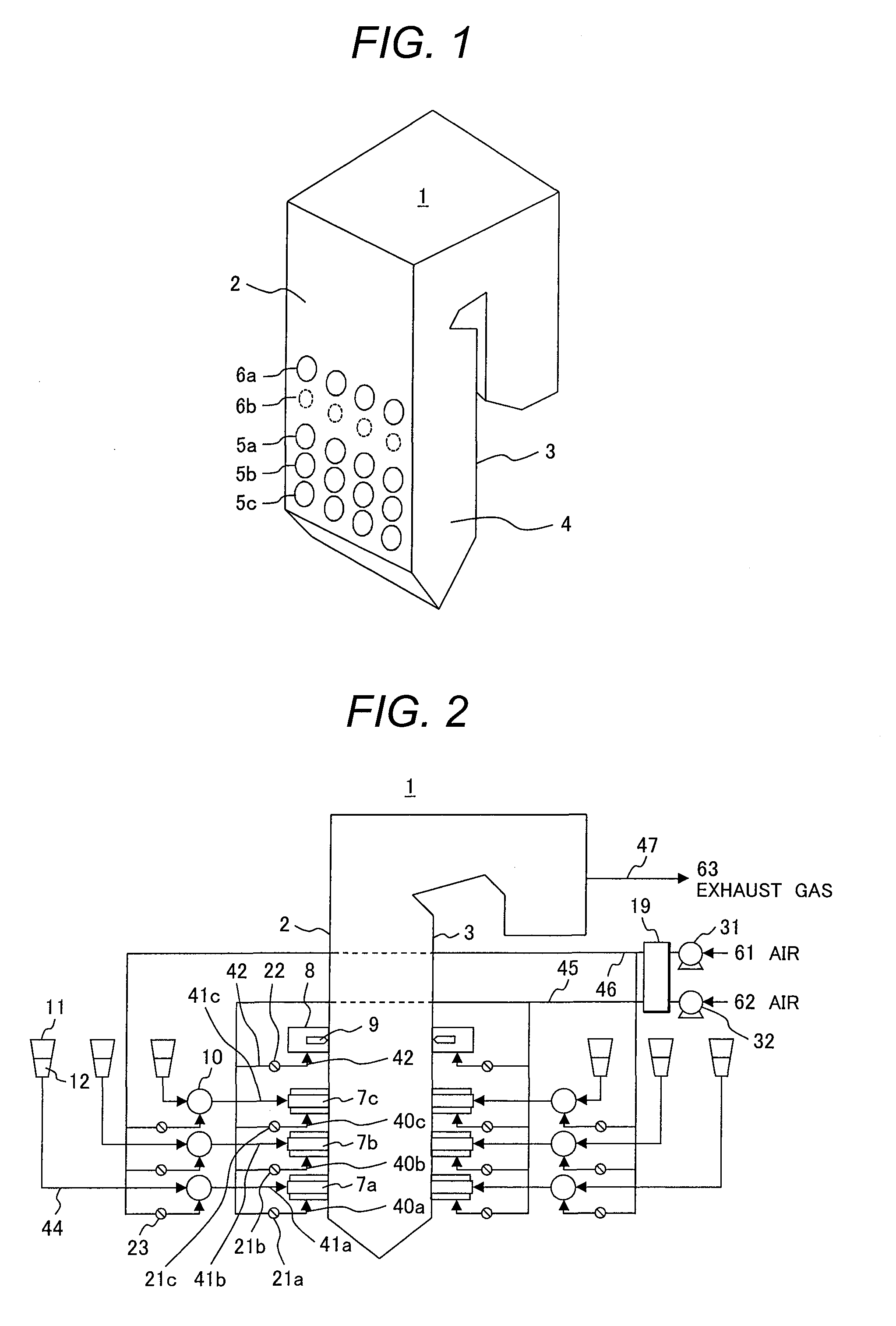
At first, the structure of a furnace of a pulverized coal boiler for the present invention will be described using FIG. 1.

In the pulverized coal boiler shown in FIG. 1, furnace walls making up a furnace 1 include a furnace front wall 2, a furnace back wall 3 opposing the furnace front wall 2, and furnace side walls 4 which are the both side walls between the furnace front wall 2 and the furnace back wall 3; and these furnace walls surround the furnace 1 to form a furnace combustion space for burning pulverized coal fuel in the furnace 1.

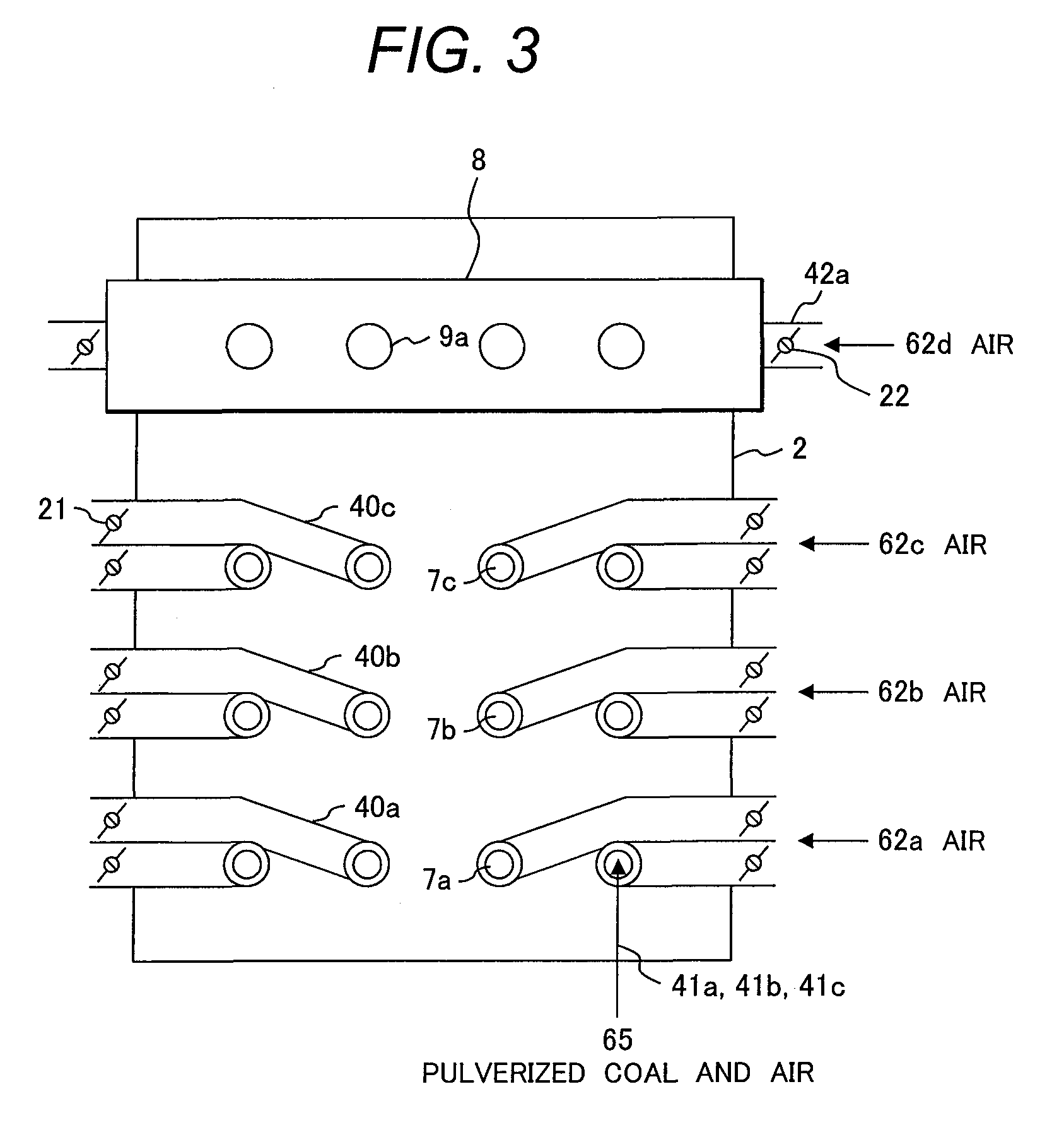
Three stages of openings (upper stage openings 5a, middle stage openings 5b, and lower stage openings 5c) for installing burners are provided in the lower portions of the furnace front wall 2 and the furnace back wall 3. Four o...

embodiment 2

Next, a method for retrofitting a pulverized coal boiler in the air combustion boiler system into a pulverized coal boiler in the oxyfuel combustion boiler system according to another embodiment of the present invention will be described using FIGS. 9 and 10.

For the method for retrofitting a pulverized coal boiler in the air combustion boiler system before retrofit shown in FIG. 9 is retrofitted into the pulverized coal boiler in the oxyfuel combustion boiler system shown in FIG. 10 according to the present embodiment, since the overall structure of the pulverized coal boiler according to the present embodiment shown in FIG. 10 has some common components with the method for retrofitting the pulverized coal boiler into the oxyfuel combustion boiler system in the previous embodiment shown in FIG. 4, the common components between them are not described and only different components in the present embodiment are explained below.

A method for retrofitting a pulverized coal boiler having t...

embodiment 3

Next, a method for retrofitting a pulverized coal boiler in which a pulverized coal boiler in the air combustion boiler system is retrofitted into a pulverized coal boiler in the oxyfuel combustion boiler system according to yet another embodiment of the present invention will be described using FIGS. 11 and 12.

For the method for retrofitting a pulverized coal boiler in which the pulverized coal boiler in the air combustion boiler system before retrofit shown in FIG. 11 is retrofitted into the pulverized coal boiler in the oxyfuel combustion boiler system shown in FIG. 12 according to the present embodiment, since the overall structure of the pulverized coal boiler shown in FIG. 12 has some common components with the method for retrofitting pulverized coal boiler in the previous embodiment shown in FIG. 4, the common components between them are not described and only different components in the present embodiment are explained below.

FIG. 11 is a partial structural view of a pulveriz...


PUM

PropertyMeasurementUnit
net thermal efficiencyaaaaaaaaaa
concentrationaaaaaaaaaa
temperaturesaaaaaaaaaa

Abstract

A method for retrofitting a pulverized coal boiler in an air combustion boiler system is disclosed, which has a plurality of burners over a plurality of stages along the vertical direction on a wall surface of a furnace of the pulverized coal boiler and an after-air port for introducing air for two-stage combustion located above the burners to retrofit into a two-stage combustion pulverized coal boiler in an oxyfuel combustion boiler system.

Description

CLAIM OF PRIORITYThe present application claims priority from Japanese patent application JP 2009-243581 filed on Oct. 22, 2009, the content of which is hereby incorporated by reference into this application.BACKGROUND OF THE INVENTION1. Field of the InventionThe present invention relates to a method for retrofitting a pulverized coal boiler in which a pulverized coal boiler in an air combustion boiler system is retrofitted into a pulverized coal boiler in an oxyfuel combustion boiler system.2. Description of Related ArtAs part of measures against global warming, a method of burning a mixture gas of highly-pure oxygen and combustion exhaust gas instead of using conventional air has been proposed for burning fuel in a boiler. Hereinafter, this method is referred to as oxyfuel combustion, and a combustion method using air is referred to as air combustion.Since the majority of exhaust gas will be CO2 in oxyfuel combustion, the exhaust gas does not require condensation for recovering CO...

Claims


Application Information

Patent Timeline
Patent Type & Authority Applications(United States)
IPC IPC(8): B21D51/24
CPCF23C9/003F23C2202/30F23L7/007F23L2900/07001Y10T29/49352Y02E20/344Y10T29/49716Y10T29/49387Y02E20/322Y02E20/32Y02E20/34
Inventor TATSUMI, TETSUMATANIGUCHI, MASAYUKISHIBATA, TSUYOSHIHAYASHI, YOSHIHARU
Owner MITSUBISHI POWER LTD
Why Eureka
Try Eureka