Compact optics for concentration and illumination systems

a technology of compact optics and illumination systems, applied in the direction of optical elements, lighting and heating apparatuses, instruments, etc., can solve the problems of mediocre performance and high cost of such systems, and achieve the effect of not allowing widespread use and high cos

Inactive Publication Date: 2011-04-28
BANYAN ENERGY INC
View PDF6 Cites 32 Cited by
  • Summary
  • Abstract
  • Description
  • Claims
  • Application Information

AI Technical Summary

Benefits of technology

[0004]A concentrator system includes a combination of optical elements comprising a concentrating element, such as a refractive and/or reflective component, a reflective and/or refractive element to redirect sunlight into a light waveguide which is constructed with a plurality of stepped reflective surfaces for efficient aggregation and concentration into a receiver unit (thermal and/or photovoltaic) and other conventional energy conversion systems. The control of the geometry of the reflective surface...

Problems solved by technology

Numerous geometries and systems have been developed, but the mediocr...

Method used


Image

  • Compact optics for concentration and illumination systems
  • Compact optics for concentration and illumination systems
  • Compact optics for concentration and illumination systems

Examples


Embodiment Construction

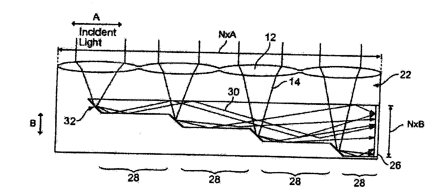
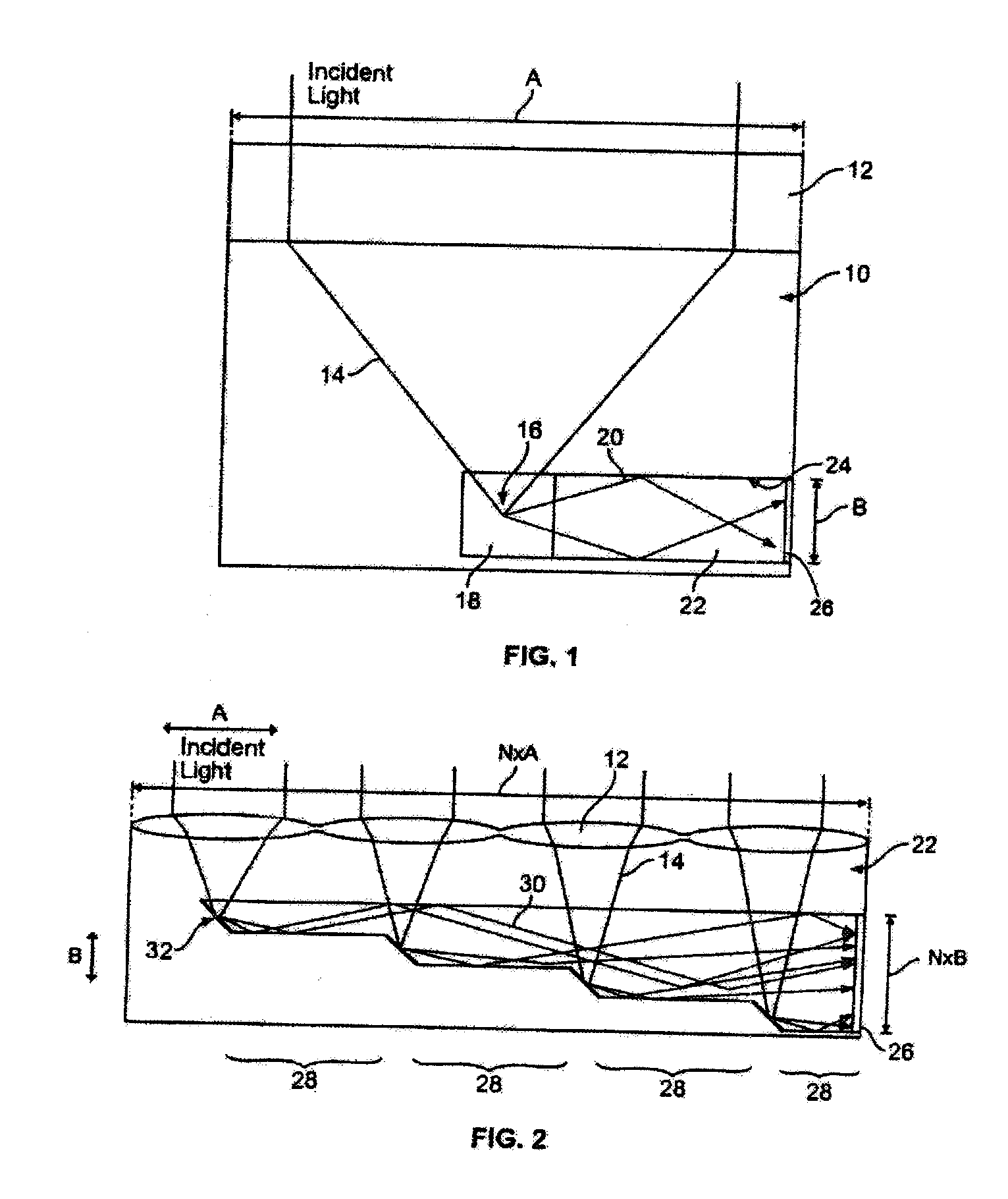
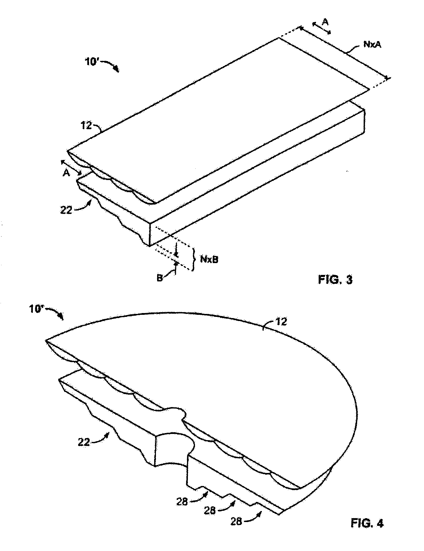
[0055]A solar energy concentrator system constructed in accordance with a preferred embodiment of the invention is indicated schematically at 10 in FIG. 1. The solar energy concentrator system 10, includes an optical concentrating element 12 which can be any conventional optical concentrator, such as an objective lens, a Fresnel lens, and / or a reflective surface element, such as a parabolic or compound shaped reflector. This optical concentrating element 12 acts on input light 14 to concentrate the light 14 to a small focal area 16. In the preferred embodiment, the small focal area 16 is disposed within reflective or redirecting component 18, or other conventional optical redirecting element which causes total internal reflection. The redirecting component 18 redirects the concentrated light 20 into a waveguide 22. The waveguide 22 is constructed to cause internal reflection of the light 20 which propagates along the waveguide 22 in accordance with Snell's law wherein total internal...


PUM


Abstract

An optical concentrator having a concentrating element for collecting input light, a redirecting element for receiving the light and also for redirecting the light, and a waveguide including a plurality of incremental portions enabling collection and concentration of the light onto a receiver. Other systems replace the receiver by a light source so the optics can provide illumination.

Description

CROSS-REFERENCE TO RELATED PATENT APPLICATIONS[0001]This application is a continuation-in-part and claims priority from U.S. patent application Ser. No. 12 / 705,434, filed Feb. 12, 2010, which is a continuation of U.S. Pat. No. 7,664,350, filed Sep. 9, 2008, which is a continuation-in-part of U.S. Pat. No. 7,672,549, filed Sep. 10, 2007, all of which are incorporated herein by reference in their entirety.[0002]This invention is directed to an optical concentrator for producing electrical, thermal and radiative energy, and also to an optical illuminator employing the structure and methods described hereinafter. More particularly, the invention is directed to a solar concentrator using a combination of optical elements to concentrate and aggregate sunlight. Other applications include lighting and illumination using the compact optics.BACKGROUND OF THE INVENTION[0003]Solar collectors have long been developed for the collection and concentration of sunlight. Increasing the energy density...

Claims


Application Information

Patent Timeline
IPC IPC(8): G02B5/09F24S23/70F24S23/00
CPCF24J2/06F24J2/067F24J2/08F24J2/18H01L31/0547G02B6/0048Y02E10/44Y02E10/52H01L31/0543G02B6/0028F24S23/00F24S23/79F24S23/12F24S23/30G02B6/124G02B6/122G02B6/12G02B6/10
Inventor GHOSH, SHONDIPSCHULTZ, DAVID SHELDONMACK, JOHN HUNTERGRIMMER, CHRISTOPHER STEPHENFINE, KEVIN RICHARD
Owner BANYAN ENERGY INC
Why Eureka
Try Eureka