
Probe for local anaesthetic system

a local anaesthetic and probe technology, applied in the field of probes for local anaesthetic systems, can solve the problems of unnecessary standby time, inability to use a proper anaesthetic method, inconvenient operation, etc., and achieve the effect of increasing the heat capacity more stably and efficiently

Inactive Publication Date: 2011-04-28
ELBIO +2
View PDF2 Cites 26 Cited by
  • Summary
  • Abstract
  • Description
  • Claims
  • Application Information

AI Technical Summary

Benefits of technology

The present invention provides a probe for a local anaesthetic system that uses a cooling method to cause no pain. The probe includes a cooling pad made of a heat conductive material with a predetermined contacting surface to cool the anaesthetic area. The cooling pad has a metal case with a thermoelement that emits cool air to the heat capacity adding means and the cooling pad. The heat capacity adding means is a liquid that increases the heat capacity of the cooling pad. The probe also includes a first temperature detector to control the thermoelement, a plurality of cooling pins to increase cooling efficiency, a cooling jacket to cool the heat-generating part of the thermoelement, a second temperature detector to transmit the detected temperature to a controller, and an alarming means to generate an alarming signal if the detected temperature exceeds a predetermined cooling starting temperature. The technical effects of the invention include efficient and stable cooling of the anaesthetic area with a cooling method that causes no pain.

Problems solved by technology

Even though such a simple operation causes considerable pain, there is not a proper anaesthetic method which can be employed easily.
Further, the injection method requires certain anaesthetic time to achieve anaesthetic effects, which takes an unnecessary standby time, and is inefficient and inconvenient.
However, it is difficult to adjust spray distance, spray time, etc.
Also, the nitrogen spray is controversial in that it generates carcinogen, and is barely used.

Method used


Image

  • Probe for local anaesthetic system
  • Probe for local anaesthetic system
  • Probe for local anaesthetic system

Examples


Embodiment Construction

[0030]Hereinafter, exemplary embodiments of the present invention will be described with reference to accompanying drawings, wherein like numerals refer to like elements and repetitive descriptions will be avoided as necessary.

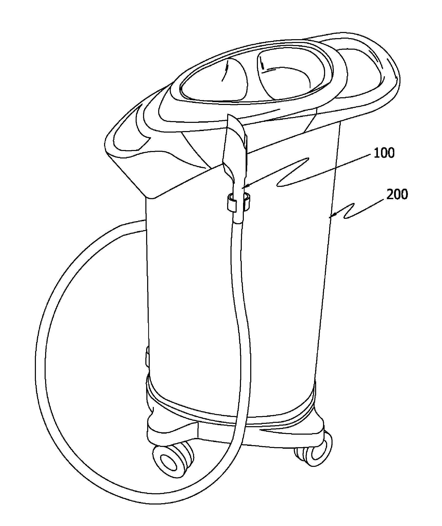
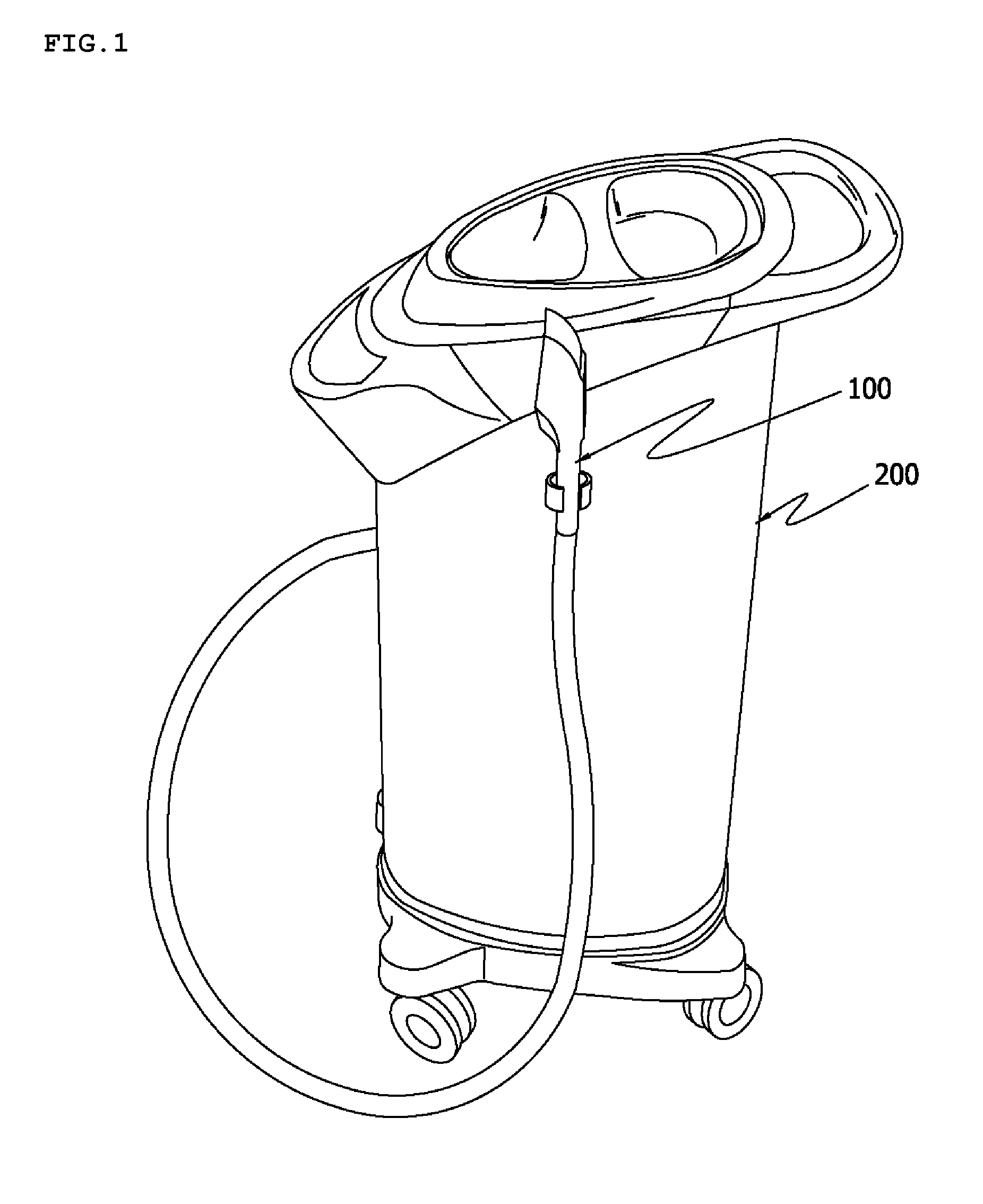
[0031]FIG. 1 is a perspective view of a probe which is installed in a local anaesthetic system according to an exemplary embodiment of the present invention.

[0032]Referring to FIG. 1, a probe 100 for a local anaesthetic system according to an exemplary embodiment of the present invention contacts a local area of the skin, cools down the skin layer and blocks a transmission of a pain to the nerve to thereby perform an anaesthetic operation. The probe 100 is electrically and physically connected with a main body 200 of the local anaesthetic system through a cable and a coolant line.

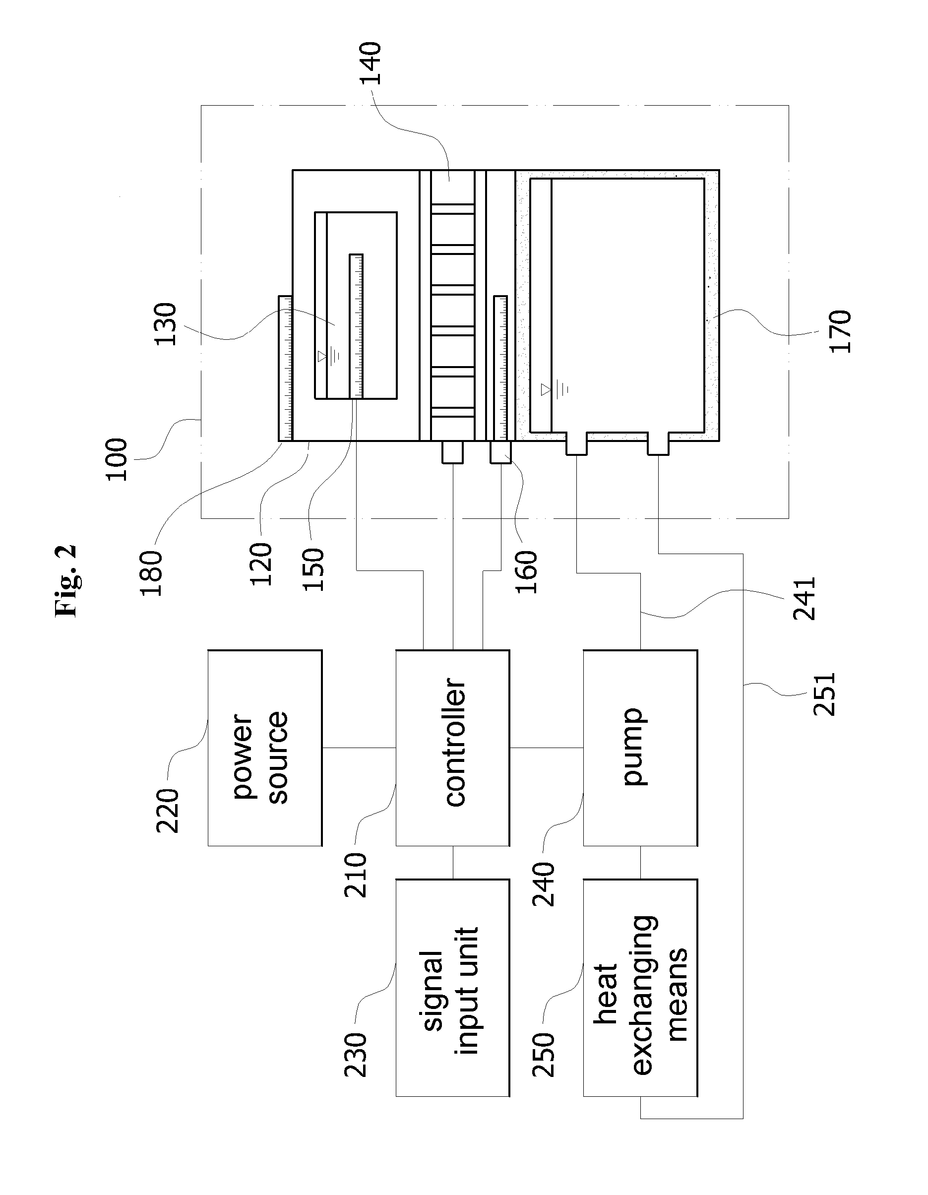
[0033]FIG. 2 is a block diagram of the probe 100 for the local anaesthetic system according to the exemplary embodiment of the present invention. FIG. 3 is an exploded perspective vie...


PUM


Abstract

The present invention relates to a probe for a local anaesthetic system, and more particularly, to a probe for a local anaesthetic system which cools a local area of the body to perform a local anaesthetic operation without difficulty. The present invention provides a probe for a local anaesthetic system which cools a local area to be anaesthetized, the probe comprising a cooling pad which has a heat conductive material and a predetermined contacting surface to contact an anaesthetic area; a heat capacity adding means which is liquid to increase a heat capacity of the cooling pad; and a thermoelement which is provided to emit a cool air to at least one of the heat capacity adding means and the cooling pad. The probe performs an anaesthetic operation without pain by instantly cooling a skin layer and blocking a transmission of a pain to the nerve, and performs an anaesthetic operation repeatedly and stably by raising a heat capacity of a cooling pad with a heat capacity adding means.

Description

CROSS-REFERENCE TO RELATED APPLICATION[0001]This application claims priority from Korean Patent Application No. 10-2007-0022948, filed on Mar. 8, 2007, in the Korean Intellectual Property Office, the disclosure of which is incorporated herein by reference.BACKGROUND OF THE INVENTION[0002]1. Field of the Invention[0003]Apparatuses consistent with the present invention relate to a probe for a local anaesthetic system, and more particularly, to a probe for a local anaesthetic system which cools a local area of the body to perform a local anaesthetic operation without difficulty.[0004]2. Description of the Related Art[0005]Generally, if a medical practice such as surgery and treatment or a skin care is expected to give a pain to patients, anaesthetia is performed to patients to block the transmission of the pain to the nerve and remove or lower the pain.[0006]As the anaesthetia is accompanied by side effects, it is used within a limited range such as long-time surgery or treatment, or a...

Claims


Application Information

Patent Timeline
Patent Type & Authority Applications(United States)
IPC IPC(8): A61F7/00
CPCA61F7/10A61F2007/0285A61F2007/0095A61F2007/0059A61B18/02A61H39/06
Inventor KIM, DONG WOO
Owner ELBIO
Learn More