Process to obtain thermal and kinetic energy from a geothermal heat source using supercritical co2

a geothermal heat source and supercritical technology, applied in the direction of mechanical power devices, machines/engines, geothermal energy generation, etc., to achieve the effect of efficient use and more energy

Inactive Publication Date: 2011-05-05
GREENFIRE PARTNERS
View PDF9 Cites 39 Cited by
  • Summary
  • Abstract
  • Description
  • Claims
  • Application Information

AI Technical Summary

Benefits of technology

[0012]Because the working fluid in the pseudo turbine is supercritical carbon dioxide, the working fluid flows like a gas. In addition, because supercritical carbon dioxide is not a solvent for the inorganic materials found in igneous and metamorphic rocks, the working fluid in the pseudo turbine does not carry dissolved minerals that could be deposited on the surfaces of the pseudo turbine as would typically occur with a hot aqueous fluid. Thus, the use of supercritical carbon dioxide makes it possible to efficiently use the pseudo turbines in the geothermal systems of the present invention.
[0013]In addition, the expansion of the supercritical carbon dioxide in the pseudo turbine may be carried out so as to produce a liquid carbon dioxide or supercritical carbon dioxide, rather than gaseous carbon dioxide. Expanding the supercritical carbon dioxide without reaching a gas avoids the need to condense gaseous fluid, (unlike steam generation systems). With the carbon dioxide in a liquid or supercritical state, the carbon dioxide fluid can be economically pumped back into the hot rock reservoir. The combination of using a pseudo turbine with a heat exchanger in a binary system configuration produces more energy than thermal methods alone while still allowing closed loop cycling of the carbon dioxide working fluid.

Problems solved by technology

In addition, because supercritical carbon dioxide is not a solvent for the inorganic materials found in igneous and metamorphic rocks, the working fluid in the pseudo turbine does not carry dissolved minerals that could be deposited on the surfaces of the pseudo turbine as would typically occur with a hot aqueous fluid.

Method used


Image

  • Process to obtain thermal and kinetic energy from a geothermal heat source using supercritical co2
  • Process to obtain thermal and kinetic energy from a geothermal heat source using supercritical co2
  • Process to obtain thermal and kinetic energy from a geothermal heat source using supercritical co2

Examples


Embodiment Construction

[0019]I. Systems For Extracting Geothermal Energy from Hot Dry Rock Reservoir

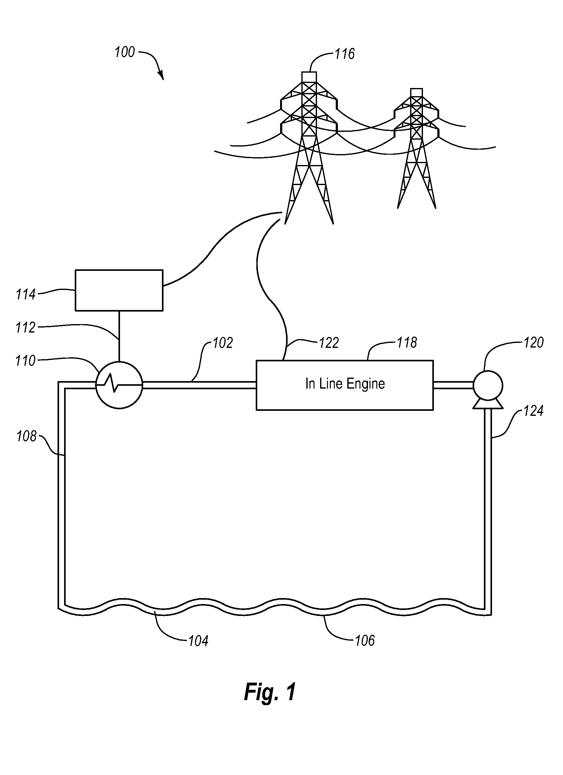
[0020]The present invention relates to the use of a pseudo turbine such as a free-piston linear engine or a turbo expander engine in a geothermal heat-mining system that utilizes supercritical carbon dioxide as the working fluid. FIG. 1 is a schematic illustration of a geothermal system incorporating a pseudo turbine according to one embodiment of the present invention. As shown in FIG. 1, a geothermal system 100 includes a closed loop fluid path 102. The fluid path 102 includes geothermally heated supercritical carbon dioxide fluid 104 in hot rock reservoir 106. The geothermally heated supercritical carbon dioxide is removed from hot rock reservoir 106 through production well 108. The geothermally heated supercritical carbon dioxide is introduced into a heat exchanger 110 to extract the geothermal energy by heating a secondary working fluid 112. The secondary working fluid 112 may be used in a power plant ...


PUM


Abstract

Methods and systems for extracting geothermal energy from an underground hot dry rock reservoir using supercritical carbon dioxide are disclosed. In a first step, the methods and systems utilize a heat exchanger in a binary system to heat a secondary fluid that is used to perform work. In a second step, the supercritical carbon dioxide is transferred to a pseudo turbine (e.g., a free-piston linear engine) to perform additional work through expansion.

Description

BACKGROUND OF THE INVENTION[0001]1. The Field of the Invention[0002]The present invention relates to the production of power and / or work from a geothermal heat source using supercritical carbon dioxide as the fluid medium in the geological formation.[0003]2. The Relevant Technology[0004]Various methods and systems exist for extracting heat from hot geothermal formations. For example one method uses water to hydraulically fracture hot rock to form a hot rock reservoir. Once a fractured reservoir has been formed, production wells are drilled to intersect the hot rock reservoir. Water is pumped into the reservoir through the injection well (i.e., typically the well used to fracture the hot rock). The injected water flows across the fractured surfaces of the hot dry rock and is heated. The geothermal heat is transferred to the surface by flowing the water upward through one or more production wells.[0005]At the surface, the heat contained in the circulating geofluid is used to generate ...

Claims


Application Information

Patent Timeline
Patent Type & Authority Applications(United States)
IPC IPC(8): F03G4/00
CPCY02E10/10F03G7/04F24T10/20
Inventor MUIR, JOHN R.EASTMAN, ALAN D.MUIR, MARK P.
Owner GREENFIRE PARTNERS
Why Eureka
Try Eureka