Gas supply apparatus equipped with vaporizer

a technology of gas supply apparatus and vaporizer, which is applied in the direction of machines/engines, pipe heating/cooling, transportation and packaging, etc., can solve the problems of bringing about decomposition and deposition of liquid sources (materials), difficult to accurately control gas flow rate, and large error in vaporized gas flow rate, so as to achieve stable flow rate control, reduce pressure fluctuation in the vaporizing chamber due to the remaining liquid content, and perform highly accurate gas flow rate control.

Active Publication Date: 2011-05-05
FUJIKIN INC
View PDF10 Cites 28 Cited by
  • Summary
  • Abstract
  • Description
  • Claims
  • Application Information

AI Technical Summary

Benefits of technology

[0028]In the present invention, because a flow rate of a gas vaporized by the vaporizer is controlled by the high-temperature type pressure type flow rate control device that has stable flow rate control characteristics, even when the conditions on the side of the vaporizer fluctuate to a certain degree, the fluctuation does not have a considerable effect on its flow rate measurement accuracy on the side of the flow rate control device. As a result, even when temperature control accuracy, or pressure control (liquid inflow control) accuracy, on the side of the vaporizer is somewhat low or fluctuated to a certain degree, its flow rate control accuracy on the side of the gas does not deteriorate in any case, which makes it possible to stably perform highly accurate gas flow rate control.
[0029]Furthermore, because the internal space of the vaporizing chamber of the vaporizer is partitioned into a plurality of compartments provided with orifices for dampening pulsation, and because the pool part for liquid content remaining inside the vaporizing chamber is provided to discharge the liquid content in the pool part to the outside, pressure fluctuation in the vaporizing chamber due to the remaining liquid content is significantly reduced.
[0030]Moreover, the pressure of the supplying gas to the flow rate control device is stabilized by providing a buffer tank between the vaporizer and the high-temperature type pressure type flow rate control device. This makes it possible to perform further highly accurate gas flow rate control.
[0031]Because the vaporizing chamber is heated by the heaters and the heat equalizing plates are installed on the outer side surfaces of the vaporizing chamber, the vaporizing chamber is uniformly heated. This makes it possible to perform more stable vaporization of the liquid content.
[0032]Because the high-temperature type pressure type flow rate control device is set to 50° C. to 200° C. by cartridge heaters, and the aluminum heat equalizing plates are attached to the main body of the high-temperature type pressure type flow rate control device, and the auxiliary sheath heaters are installed in the passage on the side of the gas inlet and are installed on the passage on the side of the gas outlet, it is possible to maintain a temperature difference between portions contacting the gas at 6° C. or less. It is also possible to completely prevent the generation of a liquid content in the flow rate control device main body.

Problems solved by technology

Meanwhile, because the liquid type thermal mass flow rate control device LMFC is used for the gas supply apparatus of FIG. 12, there is the problem that an error in a vaporized gas flow rate becomes inevitably large even when an error in flow rate control in a liquid state is small.
This makes it difficult to accurately control gas flow rate.
Furthermore, it is necessary to set a temperature of its sensor portion to be higher than a temperature of its main line in the high-temperature type thermal mass flow rate control device HMFC, which may easily bring about decomposition and deposition of the liquid source (material).
Therefore, not only is the gas supply apparatus itself increased in size by necessity, but also various inconveniences are brought about in terms of energy saving, operating cost, and the like.

Method used


Image

  • Gas supply apparatus equipped with vaporizer
  • Gas supply apparatus equipped with vaporizer
  • Gas supply apparatus equipped with vaporizer

Examples


embodiment 1

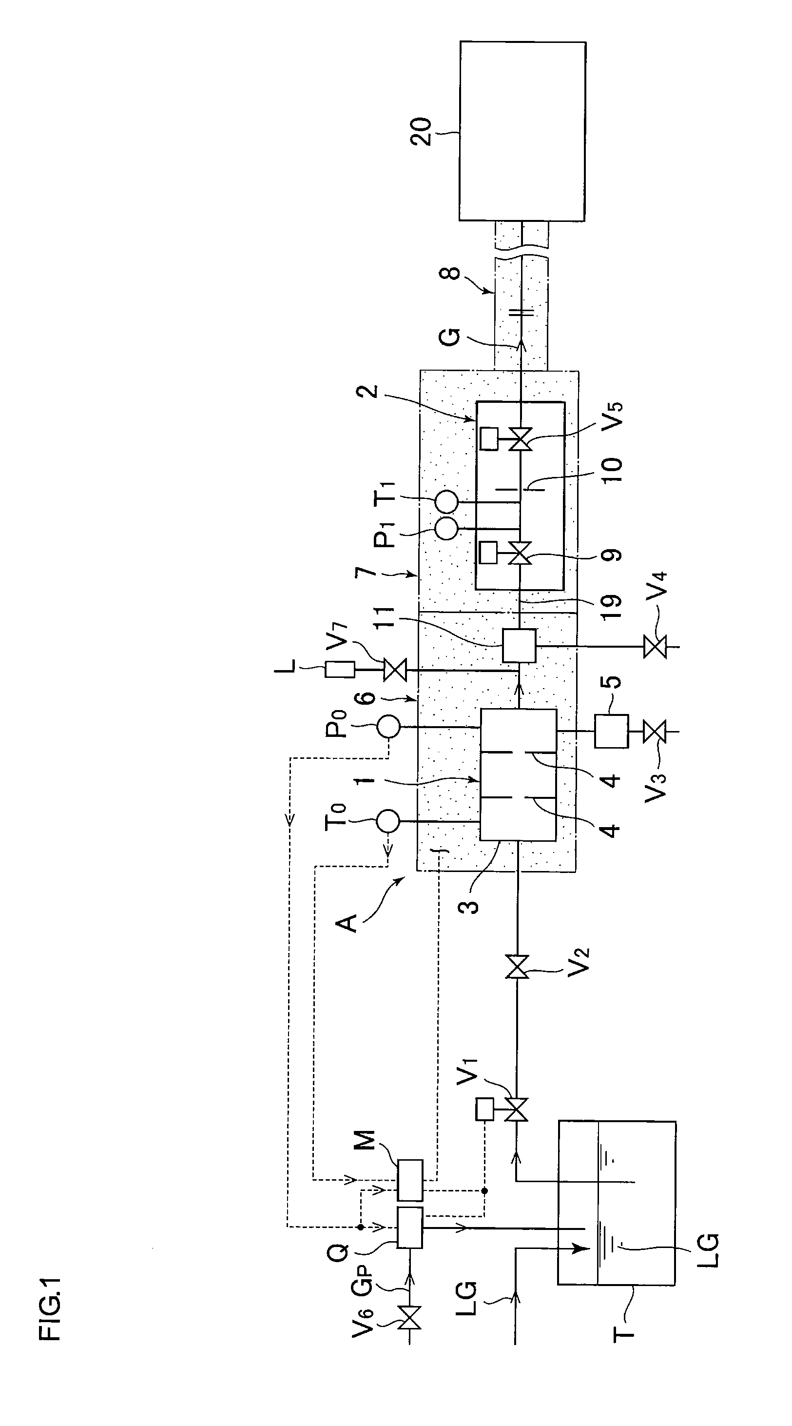
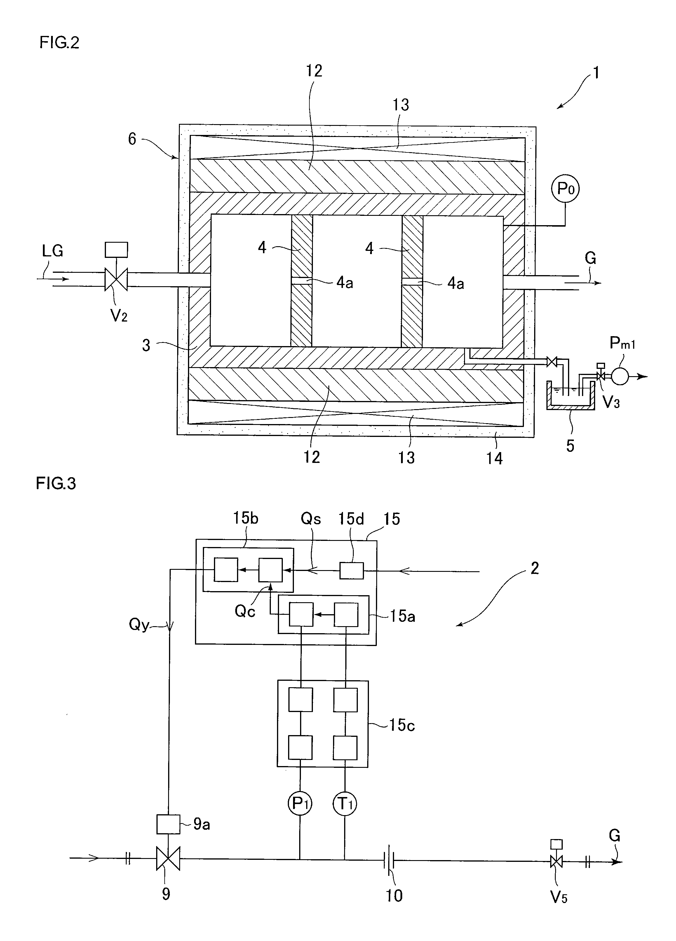
[0064]FIG. 8 is an explanatory diagram for a water vaporization experiment using the vaporizer 1 (whose internal volume is approximately 18 cm3) according to the present invention. The purified water LG in the tank T was pressure-injected into the vaporizing chamber 3 of the vaporizer 1 through an orifice 22 of size / diameter φ=0.8 mm by a pump Pm2, and heated by the heating device 6 composed mainly of an I / H heater 13 through the orifice 4a of size / diameter φ=0.2 mm and the orifice 4b of size / diameter φ=0.2 mm, and the vaporized gas (steam gas) G was passed through the high-temperature type pressure type flow rate control device 2 at a flow rate of 100 SCCM. In addition, the terminal end of a pipe passage 23 on the outlet side of the pressure type flow rate control device 2 was vacuumed by a scroll pump type vacuum pump 21.

[0065]The heating device 7 of the high-temperature type pressure type flow rate control device 2 is composed mainly of the cartridge heaters 17 (see, e.g., FIG. 4...


PUM

PropertyMeasurementUnit
temperatureaaaaaaaaaa

Abstract

An energy-saving, downsized gas supply apparatus equipped with a vaporizer is provided, wherein the gas supply apparatus is capable of stably and easily performing highly accurate gas flow rate control without requiring rigorous temperature control on the vaporizer side. The present invention pertains to a gas supply apparatus equipped with a vaporizer that includes (a) a liquid receiving tank; (b) a vaporizer that vaporizes liquid; (c) a high-temperature type pressure type flow rate control device that adjusts a flow rate of a vaporized gas; and (d) heating devices that heat the vaporizer, the high-temperature type pressure type flow rate control device, and desired portions of pipe passages connected to the vaporizer and the high-temperature type pressure type flow rate control device.

Description

[0001]This is a National Phase Application in the United States of International Patent Application No. PCT / JP2009 / 000643 filed Feb. 17, 2009, which claims priority on Japanese Patent Application No. 2008-094640, filed Apr. 1, 2008. The entire disclosures of the above patent applications are hereby incorporated by reference.FIELD OF THE INVENTION[0002]The present invention relates to improvements in a gas supply apparatus equipped with a vaporizer used for semiconductor manufacturing devices, chemical industrial facilities, medical industrial facilities, and the like, and relates to a gas supply apparatus equipped with a vaporizer having a simple structure, which makes possible energy saving and downsizing of the unit. The unit is capable of easily performing temperature management and flow rate control by combining a vaporizer and a high-temperature type pressure type flow rate control device to make use of the stable flow rate control characteristics of the pressure type flow rate...

Claims


Application Information

Patent Timeline
Patent Type & Authority Applications(United States)
IPC IPC(8): F15D1/00
CPCB01B1/005F02D19/027B01J2219/00162B01J2219/00164B01J2219/00191B01J2219/00198B01J2219/00213B01J2219/00231C23C16/4481C23C16/4485C23C16/45561F02M21/06Y02T10/32F02M21/0239F02D19/023B01J4/02Y02T10/30Y10T137/6416Y10T137/6606
Inventor NAGATA, ATSUSHINAGASE, MASAAKIHIDAKA, ATSUSHIHIRATA, KAORUMATSUMOTO, ATSUSHINISHINO, KOUJIDOHI, RYOUSUKEIKEDA, NOBUKAZU
Owner FUJIKIN INC
Why Eureka
Try Eureka