Hybrid heat exchange apparatus

Active Publication Date: 2011-05-05
EVAPCO
View PDF40 Cites 64 Cited by
  • Summary
  • Abstract
  • Description
  • Claims
  • Application Information

AI Technical Summary

Benefits of technology

[0036]In the fourth mode, when the temperature of the ambient air is warmer than in the third mode, and ambient conditions of temperature and humidity are such that evaporative heat transfer and dry heat transfer will be effective, the air inlet dampers are partially open, such that some of the ambient air flows via the second air passage through the dry heat transfer cell where it is heated and then flows through the direct heat transfer media in the evaporative heat transfer cell with the distributor assembly of cooling liquid turned on, and some of the ambient air bypasses the dr

Problems solved by technology

Evaporative coolers reject heat at temperatures approaching the lower ambient wet bulb temperatures, while dry coolers are limited to temperatures approaching the higher ambient dry bulb temperatures.
However, even in view of potentially increased process efficiencies and lower overall process energy requirements, evaporative cooling and eva

Method used


Image

  • Hybrid heat exchange apparatus
  • Hybrid heat exchange apparatus
  • Hybrid heat exchange apparatus

Examples


first embodiment

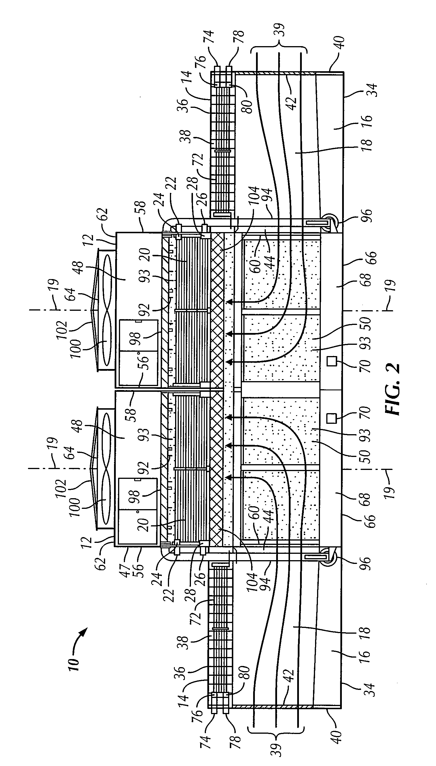
[0075]When present, the direct contact evaporative heat exchanger, typically in the form of direct contact heat transfer media 104, which is known as wet deck fill, provides direct, evaporative heat exchange when the air flow and the evaporative water or other cooling liquid come into direct contact with each other and are mixed with some desired degree of turbulence within the wet deck fill heat transfer media 104, when used. The turbulent mixing of the air and water in the heat transfer media 104 allows for greater heat transfer between the air and water, but the benefits of the increased turbulent mixing in the media 104 should not be overcome by potential adverse effects on the energy requirements of a larger fan motor or fan size or air flow reduction. As is well known in the art, there is a fine balance among these factors when deciding whether and what type of wet deck fill heat transfer media to use. That is why the use of the media 104 is optional in apparatus 10. When used...

third embodiment

[0130]The third alternative embodiment of the hybrid heat exchange apparatus 10″ of the present invention, shown in FIGS. 9 and 10, will now be described. Unless otherwise described specifically regarding this third embodiment of the apparatus 10″, the components and operation may be the same as described above regarding the first two embodiments of the apparatus 10 and 10′.

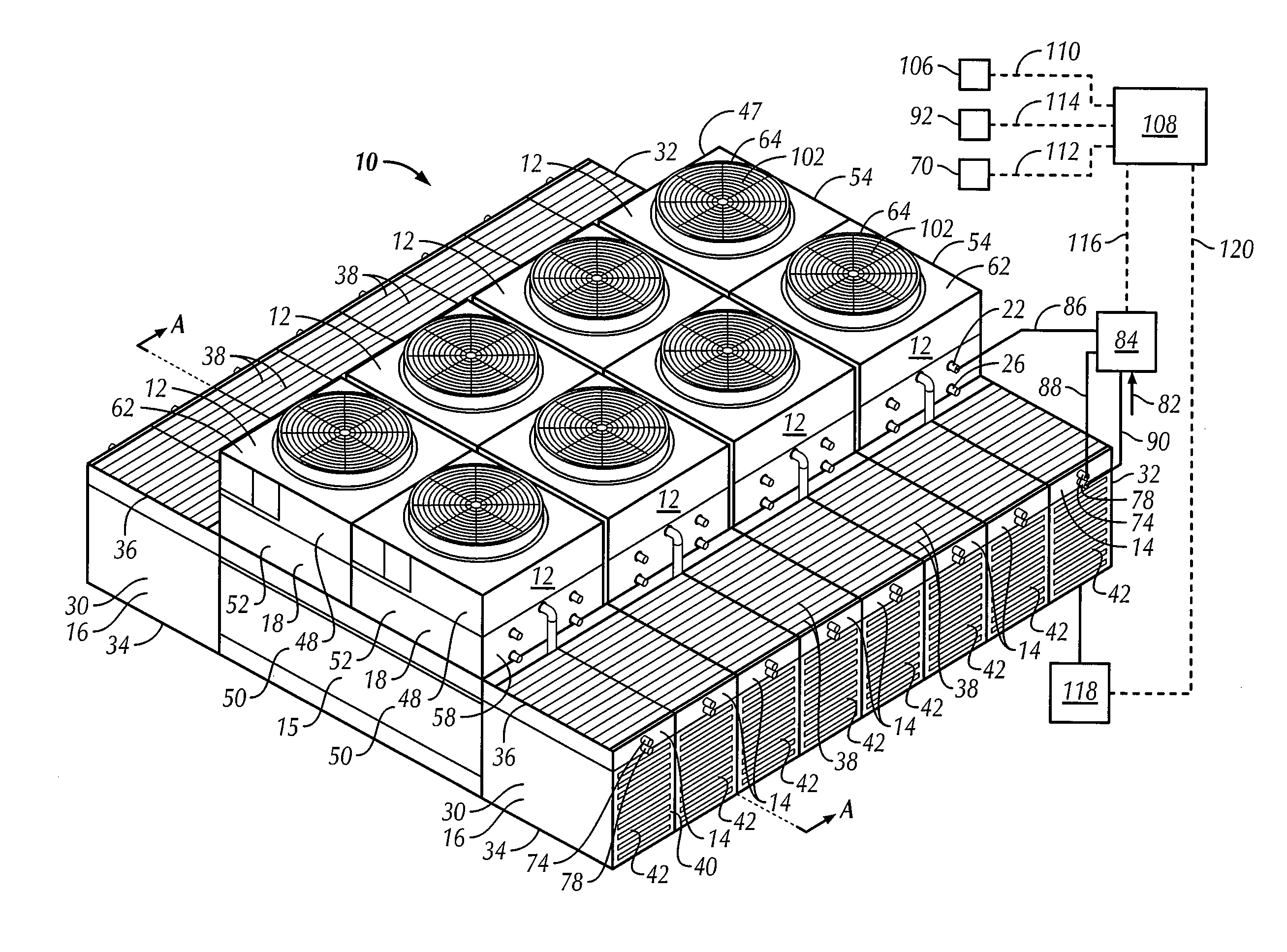
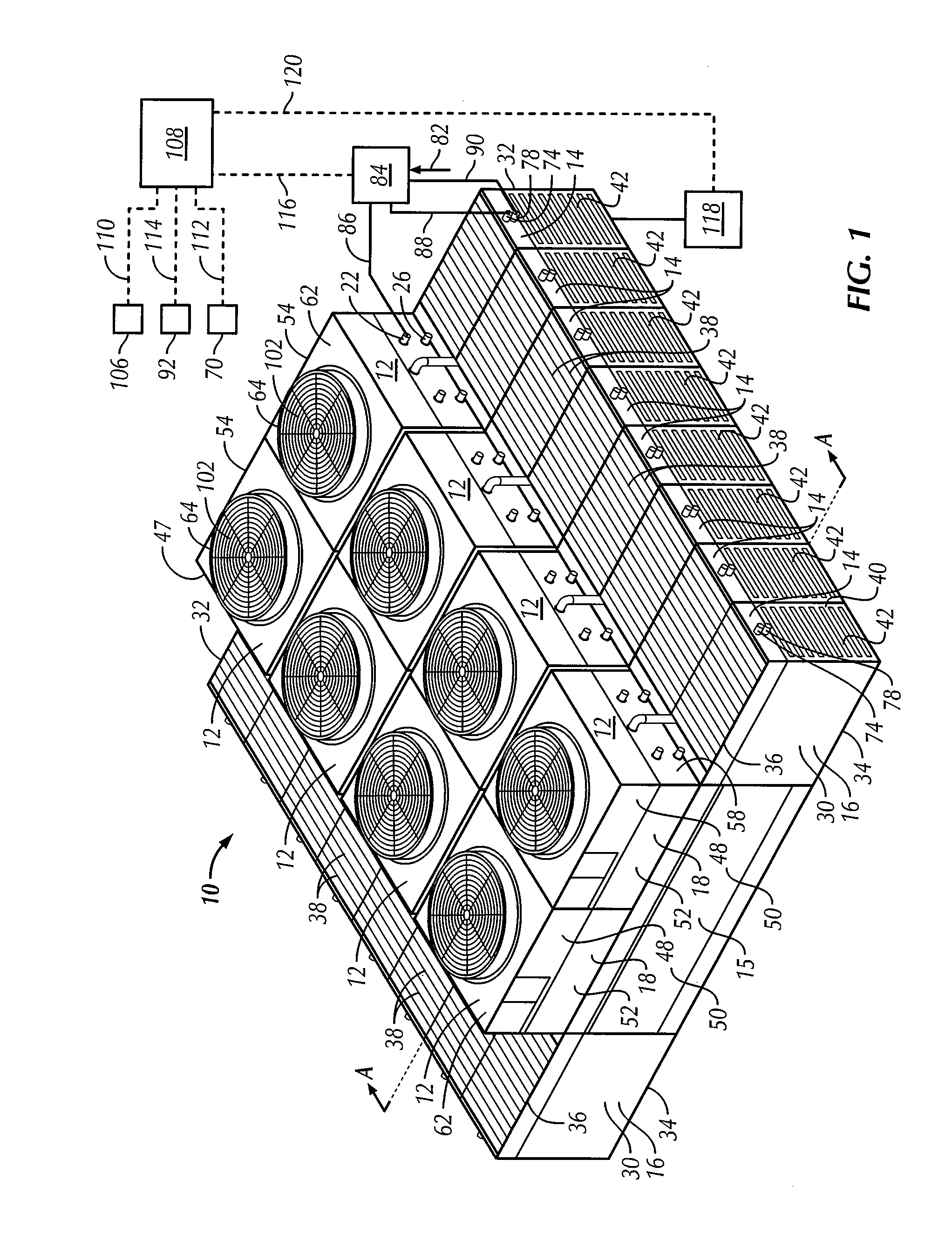
[0131]The apparatus 10″ is shown in FIGS. 9 and 10 as including two evaporative heat transfer cells 12 and two dry heat transfer cells 14, although any number of each of such cells may be used. The description will be with respect to an embodiment including one evaporative heat transfer cell 12 and one dry heat transfer cell 14, but still with reference to FIGS. 9 and 10, where the cross-section view of FIG. 2 shows one evaporative heat transfer cell 12 adjacent to and in fluid communication with a dry heat transfer cell 14 on the opposite sides of the evaporative heat transfer cell 12. The plenum chamber housing...


PUM


Abstract

A hybrid heat exchange apparatus for indirectly transferring heat between a process fluid and ambient air includes an evaporative heat transfer cell operative in a wet mode or a dry mode, a dry heat transfer cell and a fan. The air may bypass the dry heat transfer cell to flow through a first air passage or may flow through a second air passage through the dry heat transfer cell and in either event, then through the evaporative heat transfer cell. The air may partially flow through and partially bypass the dry heat transfer cell, and then through the evaporative heat transfer cell. The evaporative heat transfer cell optionally may include a direct contact evaporative heat exchanger. Manually or automatically controlling air flow based on ambient conditions provides efficient and economical control of the hybrid heat exchange apparatus, while avoiding problems in freezing conditions.

Description

CROSS-REFERENCE TO RELATED APPLICATION[0001]This application claims the benefit under 35 U.S.C. §119(e) of U.S. Provisional Patent Application No. 61 / 258,004, filed Nov. 4, 2009, the disclosure of which is hereby incorporated herein by reference in its entirety.BACKGROUND OF THE INVENTION[0002]The present invention relates to a hybrid heat exchange apparatus or unit that may be used in different modes as a dry, sensible-heat transfer unit or as an evaporative, latent heat transfer unit, or in a combination mode using both the evaporative and dry cell operation modes, and typically may be used as a condenser to condense gaseous process fluid or as a cooler to cool process fluid in the form of a liquid or non-condensable gas at the temperatures and pressures at which the apparatus is operating.[0003]More particularly, the present invention relates to a hybrid heat exchange apparatus for indirectly transferring heat between a process fluid and ambient air and includes an evaporative he...

Claims


Application Information

Patent Timeline
IPC IPC(8): F24F7/007F24F3/14
CPCF28B1/06F28C1/06F28C1/14F28D1/0477F28F2250/06F28D5/02F28F1/36F28F27/003F28D1/0478Y02B30/70
Inventor BENZ, STEVEN M.HEGG, TREVOR H.BUGLER, III, THOMAS WILLIAMVADDER, DAVEY JOE
Owner EVAPCO
Why Eureka
Try Eureka