

Heat dissipating cavity of looped heat pipe
a heat pipe and cavity technology, applied in the direction of cooling/ventilation/heating modification, solid-state devices, semiconductor devices, etc., can solve the problems of increasing the temperature, the temperature of those electronic parts to exceed the tolerance limit, and the material used usually has low thermal conductivity coefficient, so as to achieve the effect of efficient heat dissipation
- Summary
- Abstract
- Description
- Claims
- Application Information
AI Technical Summary
Benefits of technology
Problems solved by technology
Method used
Image

Examples
Embodiment Construction
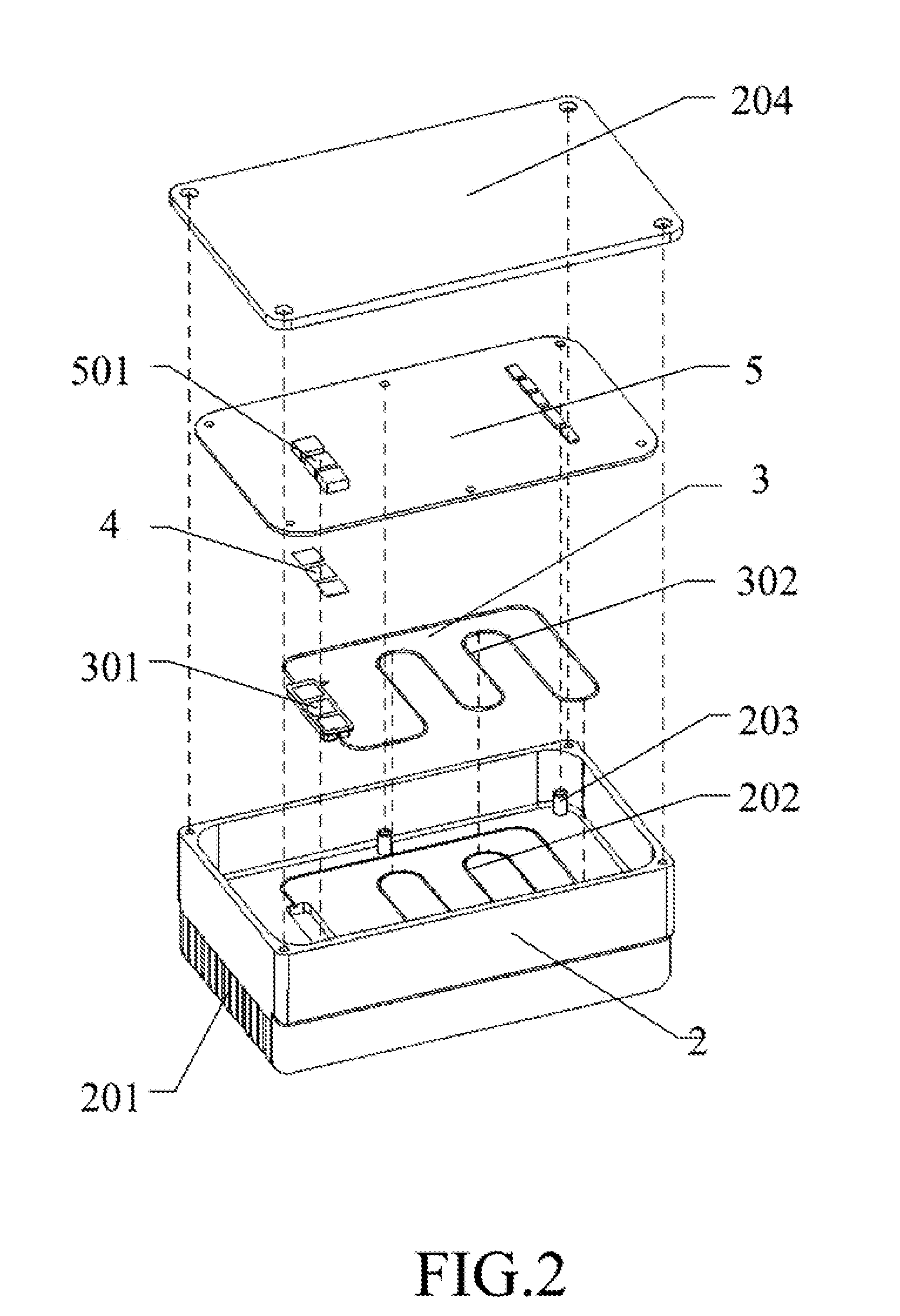
[0018]Several aspects of the invention are hereinafter described in detail with reference to FIGS. 2 to 4.
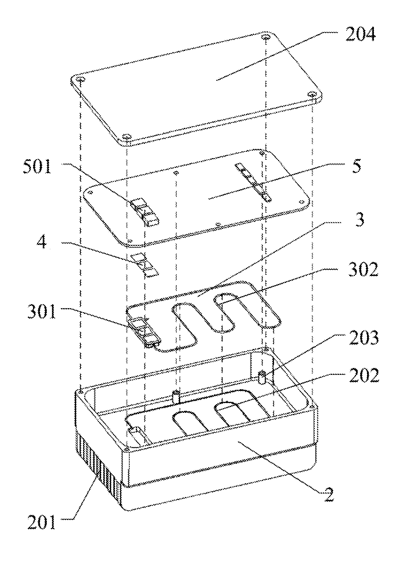
[0019]Referring to FIG. 2, the present invention is a heat dissipating cavity of looped heat pipe structure. The preferred embodiment includes a cavity 2, a looped heat pipe 3, and functional accessories (high thermal conductive elements 4 are employed in the present invention). On the outside of the cavity is disposed a plurality of heat dissipating fins 201. On the inner base of the cavity 2 is disposed a groove 202 to hold the looped heat pipe. The present invention is designed for the electronic board 5, whereon are disposed heating elements 501.
[0020]In the preferred embodiment of the invention, the looped heat pipe 3 can be disposed in the looped heat pipe groove 202 inside the cavity by welding, heat conductive glue, or screw. The high thermal conductive pads 4 are disposed between the heating elements 501 and the looped heat pipe 3. The heat generated by the heating elem...
PUM
 Abstract
Description
Claims
Application Information