Card-type peripheral apparatus

a peripheral device and card-type technology, applied in the direction of electrical apparatus casings/cabinets/drawers, instruments, semiconductor/solid-state device details, etc., can solve the problems of increasing power dissipation and power consumption, and achieve the effect of increasing data transfer rates and increasing power consumption

Inactive Publication Date: 2011-05-05
SONY CORP
View PDF36 Cites 77 Cited by
  • Summary
  • Abstract
  • Description
  • Claims
  • Application Information

AI Technical Summary

Benefits of technology

However, it should be noted here that the use of the serial interfacing, for example, tends to significantly increase data transfer rates,

Problems solved by technology

However, it should be noted here that the use of the serial interfacing, for example, tends to significantly increase data transfer rates, thereby increasing the power consumption caused by the raised controller operation clock rates and the parallel/ser

Method used


Image

  • Card-type peripheral apparatus
  • Card-type peripheral apparatus
  • Card-type peripheral apparatus

Examples


first embodiment

1. The First Embodiment

Now, referring to FIGS. 3A and 3B, there are shown external perspective views of a card-type peripheral apparatus (or a memory card) practiced as the first embodiment of the invention. FIG. 3A is a perspective view of the card-type peripheral apparatus as seen from a first side. FIG. 3B is a perspective view of the card-type peripheral apparatus as seen from a second side.

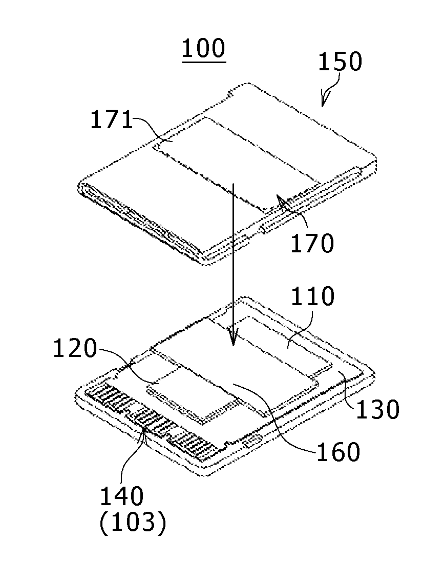
FIGS. 4A and 4B show an exemplary internal configuration of the card-type peripheral apparatus associated with the first embodiment. FIG. 4A is an exploded perspective view indicative of the internal configuration. FIG. 4B is a simplified cross section indicative of a heat release structure section of the card-type peripheral apparatus mentioned above.

FIG. 5 shows an exemplary circuit configuration of the card-type peripheral apparatus mentioned above.

First, the outlines of the configuration and function of the card-type peripheral apparatus (or the memory card) 100 associated with the embodi...

second embodiment

2. The Second Embodiment

FIGS. 7A and 7B are external perspective views of a card-type peripheral apparatus (or a memory card) practiced as the second embodiment of the invention. FIG. 7A is a perspective view of this card-type peripheral apparatus as seen from a fist side. FIG. 7B is a perspective view of this card-type peripheral apparatus as seen from a second side.

FIGS. 8A, 8B, and 8C show an exemplary internal configuration of the card-type peripheral apparatus of the second embodiment. FIGS. 8A and 8B are exploded perspective views of the internal configuration. FIG. 8C is a simplified cross section indicative of a heat release structure section.

A memory card 100A of the second embodiment differs from the memory card 100 of the first embodiment in that a heat release area based on a second thermal conductive material is arranged at two locations on the both rim sides along the length of the memory card 100A by avoiding the center section of the memory card.

To be more specific, ...

third embodiment

3. The Third Embodiment

FIGS. 9A and 9B show an exemplary internal configuration of a card-type peripheral apparatus practiced as a third embodiment of the invention. FIG. 9A is an exploded perspective view indicative of the internal configuration. FIG. 9B is a simplified cross section indicative of a heat release structure section.

A memory card 100B of the third embodiment differs from the memory card 100A of the second embodiment in that a first thermal conductive material 160A is arranged immediately below a heat generating body that is a second electronic package 120 mounted on a circuit board 130.

In this example, as shown in FIG. 7B, second thermal conductive materials 170B-1 and 170B-2 having contactors are formed on both sides of a second surface 152 of a case body 150A.

According to the third embodiment, substantially the same effects as those of the second embodiment can be attained.


PUM

PropertyMeasurementUnit
Timeaaaaaaaaaa
Lengthaaaaaaaaaa
Electrical conductoraaaaaaaaaa

Abstract

Disclosed herein is a card-type peripheral apparatus including: a case body configured to accommodate an electronic package including a circuit board between a first surface and a second surface that are opposite to each other; a first electronic package including a memory mounted on the circuit board; a second electronic package including an electronic part for controlling the memory mounted on the circuit board; a first thermal conductive material arranged inside the case body, the first thermal conductive material in contact with a surface of at least one of the first electronic package and the second electronic package; and a second thermal conductive material formed with the first surface and the second surface of the case body, wherein the first thermal conductive material and the second thermal conductive material are in contact with each other inside the case body.

Description

BACKGROUND OF THE INVENTION1. Field of the InventionThe present invention relates to a card-type peripheral apparatus, such as a memory card, for example.2. Description of the Related ArtGeneral-purpose memory cards are not so high in internal temperature rise caused by the power dissipation upon operation. This is an indication that the data transfer rates of these memory cards are not so high.With those memory cards enhanced in data transfer rates, the heat dissipation thereof is achieved by the natural dissipation from the card surfaces and from the contact of a signal terminal and a power supply terminal of each card with connector contact pins of a connector in which the memory card is inserted.The heat generated from the memory card is transmitted to a circuit board or the like over these connector contactors for heat dissipation, thereby holding down the rise of temperature internal to the memory card with an allowable range.SUMMARY OF THE INVENTIONHowever, it should be noted...

Claims


Application Information

Patent Timeline
IPC IPC(8): H05K5/02
CPCH01L2924/0002H05K7/20436H05K7/20518H05K1/0203H01L23/42H01L23/4093H01L23/3675Y10T29/49128H05K2201/10159H01L2924/00
Inventor AOKI, YOSHITAKAKIMURA, HITOSHI
Owner SONY CORP
Why Eureka
Try Eureka