Edge card connector having solder balls and related methods

a technology solder balls, which is applied in the direction of printed circuits, line/current collector details, electrical apparatus, etc., can solve the problems of affecting the performance of edge card connectors, affecting the design of high-speed digital signaling in computer system design, and affecting the design of high-speed digital signaling. achieve the effect of improving rigidity and reliability, and improving signal performan

Inactive Publication Date: 2011-05-05
HINKLE JONATHAN R
View PDF12 Cites 4 Cited by
  • Summary
  • Abstract
  • Description
  • Claims
  • Application Information

AI Technical Summary

Benefits of technology

[0008]Objects of the present invention include the following: providing edge card connectors having solder balls and related methods; providing edge card connectors having improved signal performance; and, providing a means of mounting edge card connectors with improved rigidity and reliability. These and other objects and advantages of the invention will become apparent from consideration of the following specification, read in conjunction with the drawings.
[0009]According to one aspect of the invention, an edge card connector comprises:
[0010]a substantially rigid, insulating housing having a plurality of internal electrical contacts configured to engage the edge of a first circuit board inserted into the housing;
[0011]a plurality of solder balls arranged on an outer surface of the housing in a selected pattern to establish connections to corresponding conductive pads on a second circuit board when the solder balls are at least partially melted; and,
[0012]electrical connections between the internal electrical contacts and the solder balls.
[0013]According to another aspect of the invention, an edge card connector system comprises:

Problems solved by technology

At high frequencies used today both of these technologies have poor electrical performance inherent to the method of their design.
This unwanted capacitance is deleterious to high speed digital signaling in computer system design.
These two DIMM socket technologies also make adding signals to evolutionary memory busses much more difficult.
Making them smaller pitch to fit more pins into the same space can cause significant manufacturing issues.
In addition these two DIMM socket technologies may require manual insertion into the PWB board plated holes to avoid bent pins during assembly and may be difficult to remove from the PWB board for rework should the socket become damage through mishandling.
However, the “surface mount” socket also has electrical performance issues.
Thus, these sockets are still not sufficient for supporting the evolutionary increase of high-speed digital signaling rates for modular main memory sub-systems.
Additionally, the pad and gull-wing pin method of attaching to the computer system board makes additional interconnect more difficult as well, reducing signal effectiveness and power delivery to the DIMM.

Method used


Image

  • Edge card connector having solder balls and related methods
  • Edge card connector having solder balls and related methods
  • Edge card connector having solder balls and related methods

Examples


Embodiment Construction

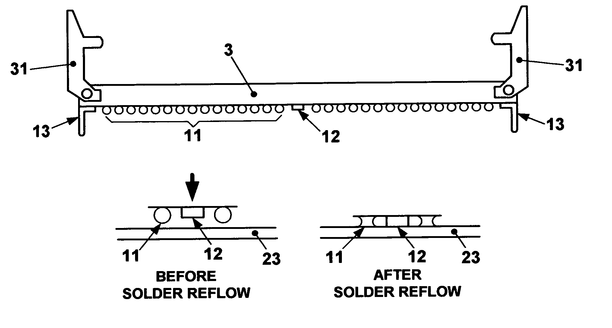
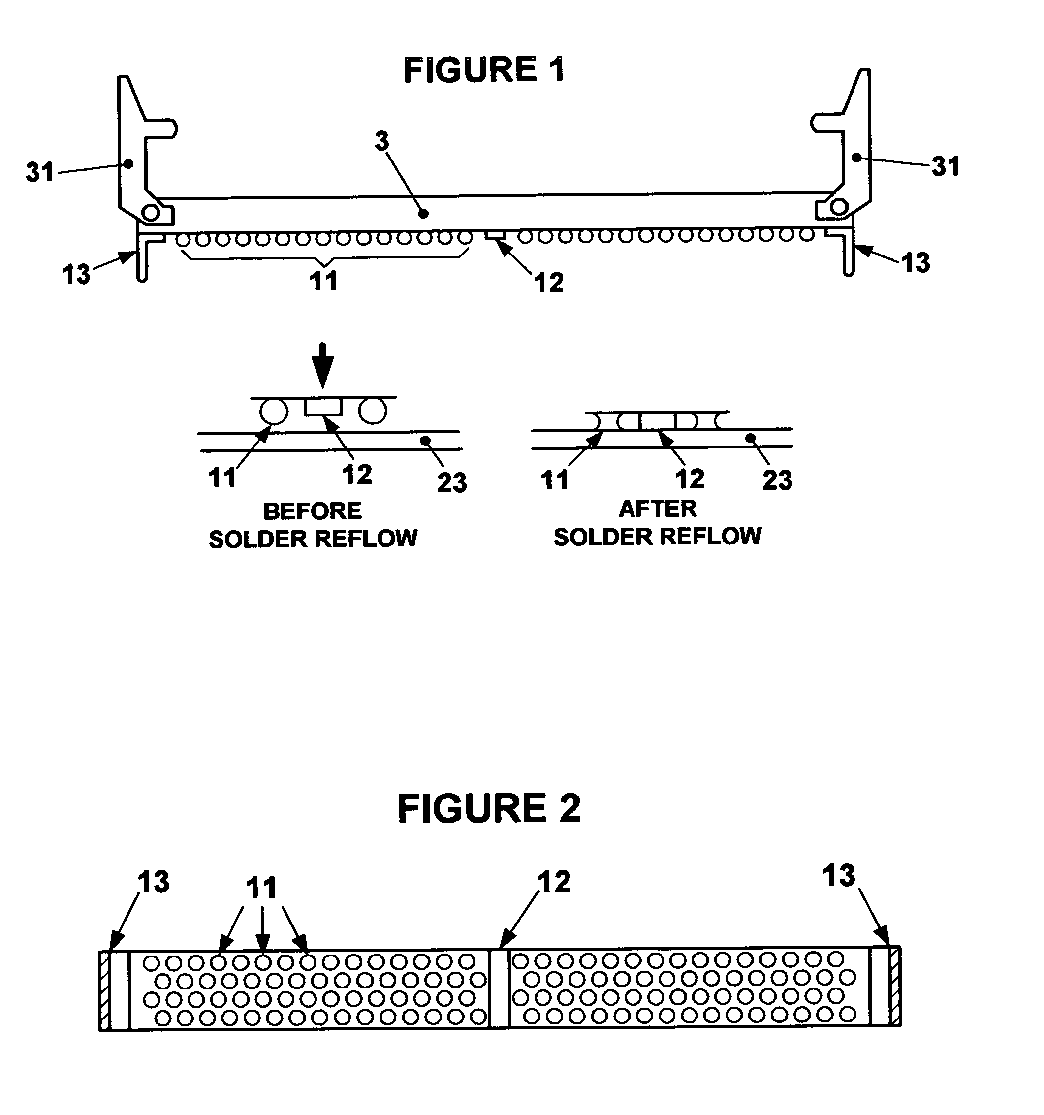
[0031]According to one example of the invention, an edge card connector can include a housing comprising a substantially rigid, insulative portion, preferably made of a dielectric material such as thermoplastic or other suitable nonconductive material. The edge card connector can also include a plurality of solder balls connected to contacts or conductive pads on the insulative portion of the housing in a selected pattern for engaging corresponding conductive pads on a circuit board such that an electrical connection is established between the solder balls and the conductive pads when at least a partially melted portion of each solder ball is contacting a respective conductive pad.

[0032]In an exemplary edge card connector in accordance with the invention, an edge card connector may have one or more solder balls or a ball grid array (BGA) interconnect for electrically coupling to a circuit board. The socket may have one or more rows of solder balls across the length of the socket, wh...


PUM


Abstract

An edge card connector includes: a substantially rigid, insulating housing having internal electrical contacts to engage the edge of a first circuit board inserted into the housing; solder balls arranged on an outer surface of the housing in a selected pattern to establish connections to corresponding conductive pads on a second circuit board when the solder balls are at least partially melted; and, electrical connections between the internal electrical contacts and the solder balls. The socket may contain additional features for added strength, ease of assembly, and other purposes. The system is assembled by placing the socket onto a circuit board, aligning the solder balls with respective contact pads, and fusing the solder balls to establish electrical connectivity. A standoff structure may be provided to avoid excessive compaction of the solder balls.

Description

CROSS-REFERENCE TO RELATED APPLICATION[0001]This application claims the benefit of Provisional Patent Application No. 61 / 009,781 by the present inventor, filed on Nov. 2, 2008, the entire disclosure of which is incorporated herein by reference.BACKGROUND OF THE INVENTION[0002]1. Field of the Invention[0003]The invention pertains to circuit board connectors. More particularly, the invention pertains to edge card connectors having solder balls and related methods of assembly.[0004]2. Description of Related Art[0005]In modern computer systems, the main memory sub-system often uses pluggable memory modules. These are generally printed wiring boards (PWBs) with memory devices mounted on them, and are called dual inline memory modules (DIMMs); they interface with memory sockets that are mounted on the main computer PWB. The most widely adopted interface and interconnect for these pluggable modules and sockets is the “card edge” (aka “edge card”) PWB module and socket interface method. Mod...

Claims


Application Information

Patent Timeline
Patent Type & Authority Applications(United States)
IPC IPC(8): H01R12/00
CPCH01R12/57H01R43/205H01R12/721
Inventor HINKLE, JONATHAN R.
Owner HINKLE JONATHAN R
Why Eureka
Try Eureka