Thermal Type Fluid Flow Sensor and Fabricating Method

a technology of fluid flow sensor and fabricating method, which is applied in the direction of liquid/fluent solid measurement, volume metering, instruments, etc., can solve the problems of increasing the number of integrating steps, increasing the fabrication cost, and deteriorating detection accuracy of air flow, so as to increase the combustion efficiency and high accuracy

Active Publication Date: 2011-05-12
HITACHI ASTEMO LTD
View PDF5 Cites 51 Cited by
  • Summary
  • Abstract
  • Description
  • Claims
  • Application Information

AI Technical Summary

Benefits of technology

[0015]A description will simply be given of an advantage achieved by a representative feature of the present invention disclosed in the application as follows.
[0016]According to the present invention, in the air flow meter having the humidity detecting portion of a thermal resistor type, there can be provided a highly accurate thermal type fluid flow sensor measuring an absolute humidity and correcting the humidity while restraining an influence by a flow of air.
[0017]Further, a detected absolute humidity data can also be utilized for controlling an explosion timing of an engine, and can increase a combustion efficiency.

Problems solved by technology

However, the following problems are posed in the background arts described above.
According to the technology disclosed in Patent Document 1, a consideration is not given to an influence by a change in a humidity of intake air effected On the heat generating resistor and the temperature measuring resistor (heat loss) to pose a problem that a detection accuracy of the air flow is deteriorated.
However, there is needed a design in consideration of an increase in a number of parts and wirings of the elements to each other, and therefore, there poses a problem of increasing a fabrication cost by complicating a structure thereof, and increasing a number of integrating steps.
Further, according to the technology disclosed in Patent Document 3, an increase in a fabrication cost by a number of integrating steps is restrained by arranging the air flow sensor and the humidity sensor on the same element.
However, the humidity sensor of measuring a humidity detects the humidity by a change in the electrostatic capacitance, and therefore, not an absolute humidity but a relative humidity is measured.
Further, a wide area is needed for the humidity sensor of the electrostatic capacitance type for increasing a sensitivity to pose a problem of increasing a fabrication cost by an increase in a size of the element.
Therefore, there poses a problem of increasing a fabrication cost similar to Patent Document 2.
Further, as in Patent Document 3, when the humidity detecting element is arranged on the same element and at a position which is deviated from a region of a flow line of air and is hermetically closed, there poses a problem that an accuracy of the air flow sensor is deteriorated by changing a resistance value of wirings of the air flow sensor by warming up the wirings of the air flow sensor at a vicinity of the humidity detecting element by heat of the humidity detecting element heated for detecting the humidity.

Method used


Image

  • Thermal Type Fluid Flow Sensor and Fabricating Method
  • Thermal Type Fluid Flow Sensor and Fabricating Method
  • Thermal Type Fluid Flow Sensor and Fabricating Method

Examples


first embodiment

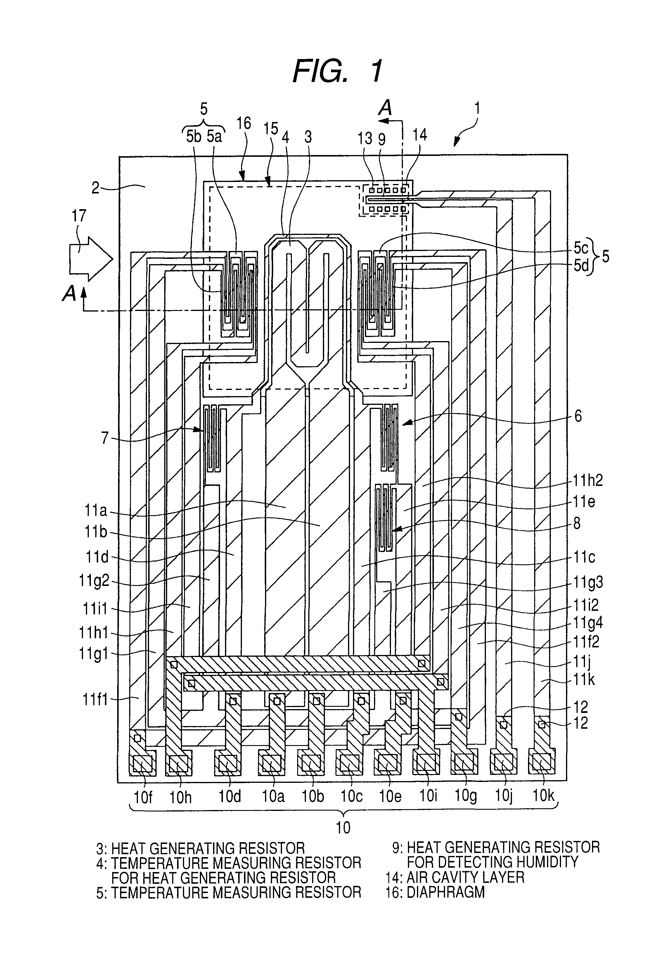
[0042]A thermal type fluid flow sensor according to the embodiment includes a humidity sensor of a thermal type formed on a substrate the same as that of an element of measuring an air flow, a drive circuit of detecting an air flow signal by supplying a current to a heat generating resistor in the element, a control circuit of calculating the air flow from the air flow signal, and a memory of storing the air flow and a correcting data of an absolute humidity, and the control circuit corrects the air flow from the absolute humidity detected by using the humidity sensor and the correcting data. Further, the thermal type fluid flow sensor according to the embodiment is used by being installed at an intake path of an internal combustion engine of an automobile or the like.

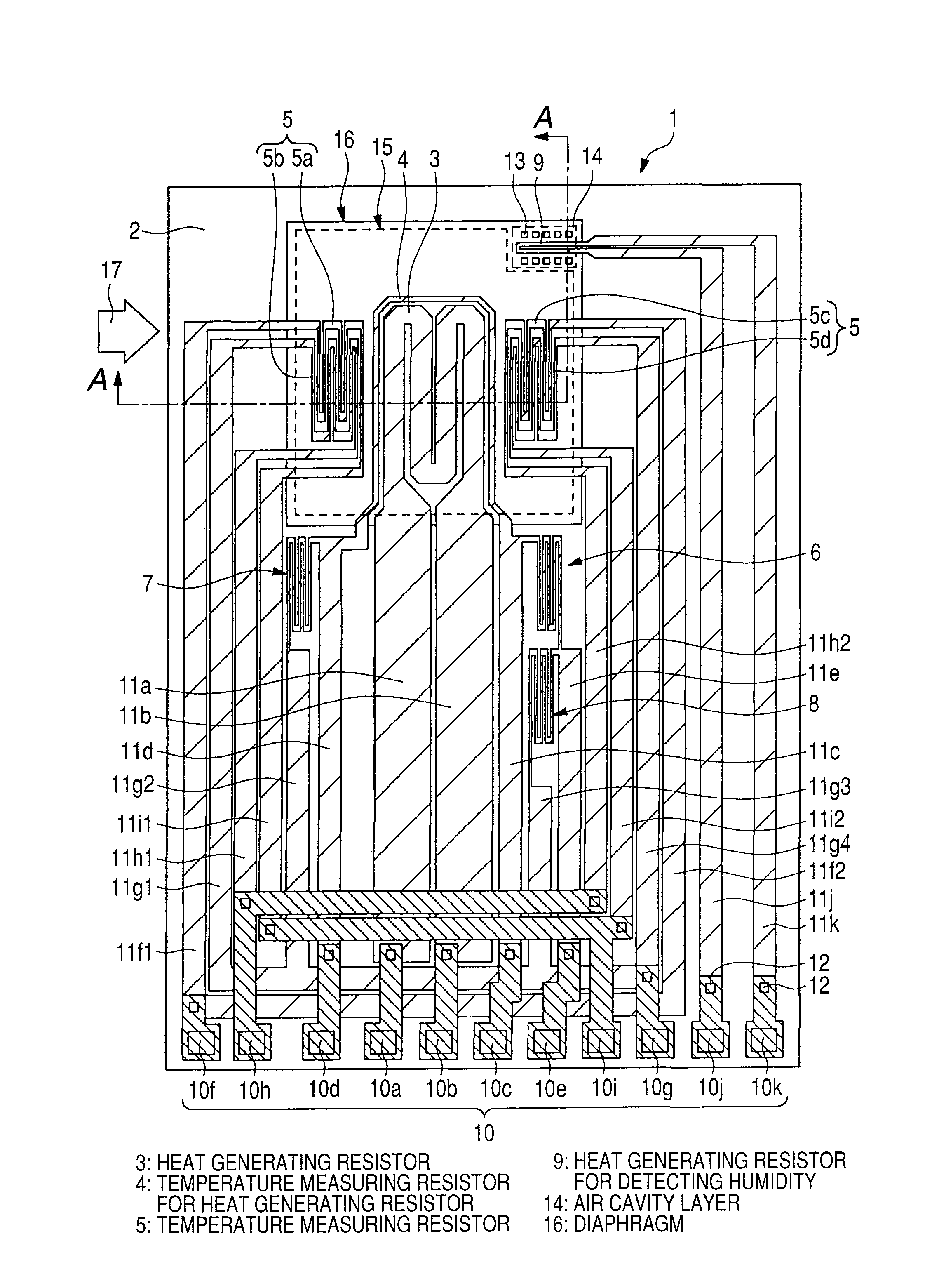
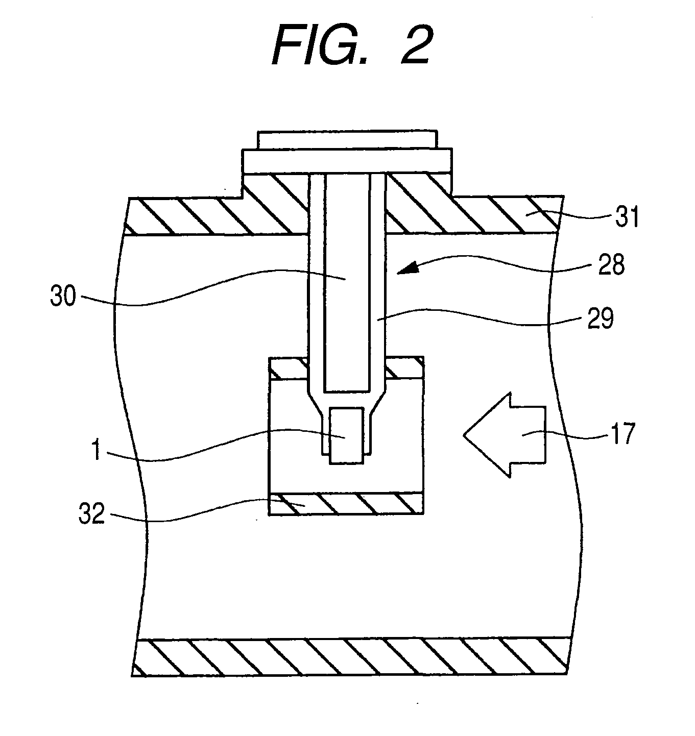
[0043]Here, FIG. 1 shows a plan view of an essential portion of the thermal type fluid flow sensor according to the first embodiment.

[0044]As shown in FIG. 1, a measuring element 1 which is a thermal type fluid flow se...

second embodiment

[0106]According to the embodiment, a description will be given of a thermal type fluid flow sensor which differs from the first embodiment in that the humidity detecting portion is formed at a diaphragm which differs from that of the air flow detecting portion.

[0107]FIG. 14 shows the thermal type fluid flow sensor according to the embodiment. The heat generating resistor 3 for detecting the air flow as well as the temperature measuring resistor 4 for the heat generating resistor, the temperature measuring resistor 5 of detecting the air flow, the air temperature measuring resistor 6 for measuring the air temperature of air, the resistors 7, 8 for controlling the heater temperature, the respective terminal electrodes for connecting the signal of the measuring element 1 to the external circuit, and the respective extension wirings are constructed by structures the same as those of the first embodiment. However, according to the thermal fluid flow sensor of the embodiment, the heat gen...


PUM

PropertyMeasurementUnit
diameteraaaaaaaaaa
widthaaaaaaaaaa
hole diameteraaaaaaaaaa

Abstract

A thermal type fluid flow sensor includes an air flow detecting portion and a temperature detecting portion formed above the same substrate, capable of correcting a humidity, and having a high measuring accuracy at a low cost, and a heat generating resistor, a temperature measuring resistor for the heat detecting resistor, a temperature measuring resistor for detecting an air flow, and a heat generating resistor for detecting a humidity are arranged in a diaphragm formed above a semiconductor substrate, an air cavity layer, and a protecting film above the air cavity layer are formed above the heat generating resistor for detecting the humidity, and the protecting film is provided with plural holes reaching the air cavity layer.

Description

CLAIM OF PRIORITY[0001]The present application claims priority from Japanese patent application JP 2009-254621 filed on Nov. 6, 2009, the content of which is hereby incorporated by reference into this application.FIELD OF THE INVENTION[0002]The present invention relates to a thermal type fluid flow sensor and fabricating method and particularly to a technology which is effectively applied to a thermal type fluid flow meter for measuring intake air of an internal combustion engine as well as a thermal type fluid flow sensor preferable for a thermal type air flow meter, and the fabricating method.BACKGROUND OF THE INVENTION[0003]At present, as a thermal type fluid flow sensor used in an air flow meter provided at an electronically controlled fuel injection apparatus of an internal combustion engine of an automobile or the like for measuring an intake air amount, a main stream is constituted by thermal type ones since a mass air amount can be directly detected thereby.[0004]Among them,...

Claims


Application Information

Patent Timeline
Patent Type & Authority Applications(United States)
IPC IPC(8): G01F1/68H01S4/00
CPCG01F1/6842G01F1/6845Y10T29/49002G01F1/6965G01F15/043G01F1/692
Inventor SAKUMA, NORIYUKI
Owner HITACHI ASTEMO LTD
Why Eureka
Try Eureka