Electro-mechanical transducer, an electro-mechanical converter, and manufacturing methods of the same

a technology of electro-mechanical converters and transducers, applied in the direction of piezoelectric/electrostrictive transducers, mechanical vibration separation, semiconductor electrostatic transducers, etc., can solve the problems of low dielectric breakdown strength of air, ecm cannot endure stronger sound pressure, and the operation of pzt in a wide frequency band is difficult, so as to achieve high degree of freedom in geometrical deformation, withstand stronger sound pressure, and high sensitivity

Inactive Publication Date: 2011-05-12
SAITAMA UNIVERSITY
View PDF5 Cites 48 Cited by
  • Summary
  • Abstract
  • Description
  • Claims
  • Application Information

AI Technical Summary

Benefits of technology

[0012]In view of the above-mentioned problems, an object of the present invention is to provide an electro-mechanical transducer and an electro-mechanical converter, both of which are flexible, having high degrees of freedom in geometri...

Problems solved by technology

The method recited in Patent Document 1, by which the ECM is directly fabricated on the semiconductor substrate, embraces the problems such that the span of the bending of the membrane area, which is allocated in the area where the semiconductor substrate is selectively removed, becomes 1/10 or more of an air gap, and because the dielectric breakdown strength of air is low, the ECM cannot en...

Method used


Image

  • Electro-mechanical transducer, an electro-mechanical converter, and manufacturing methods of the same
  • Electro-mechanical transducer, an electro-mechanical converter, and manufacturing methods of the same
  • Electro-mechanical transducer, an electro-mechanical converter, and manufacturing methods of the same

Examples


first embodiment

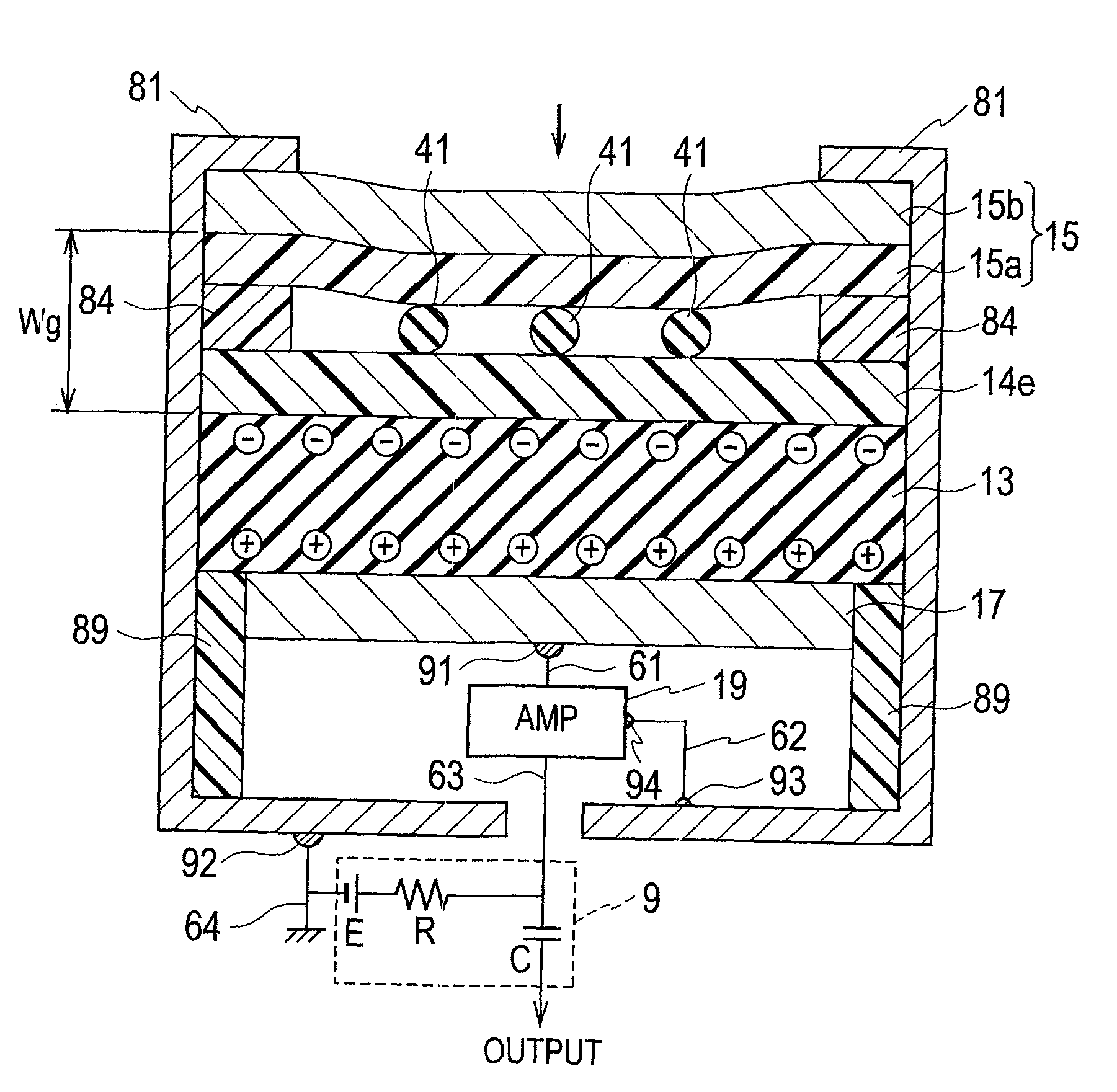
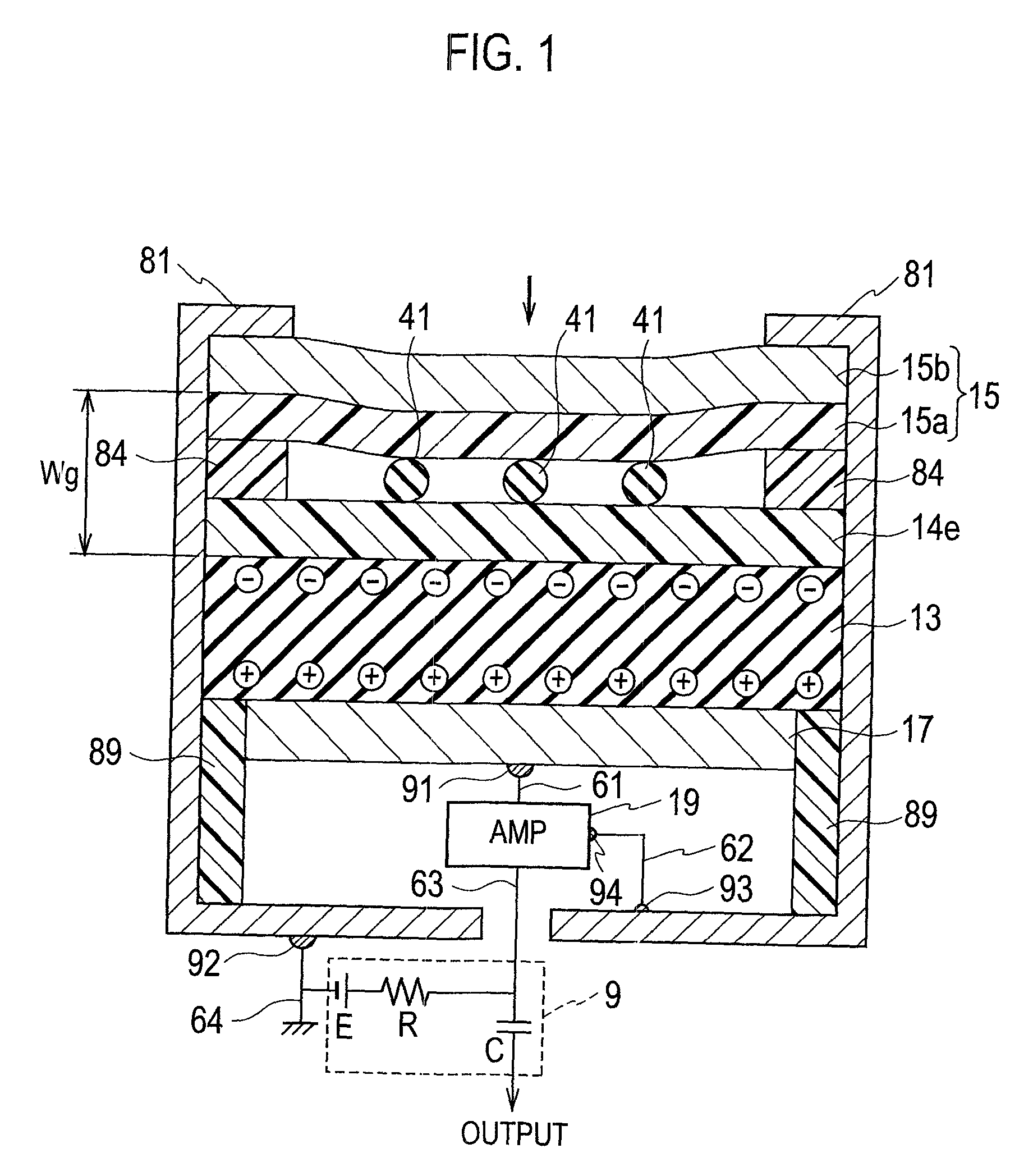
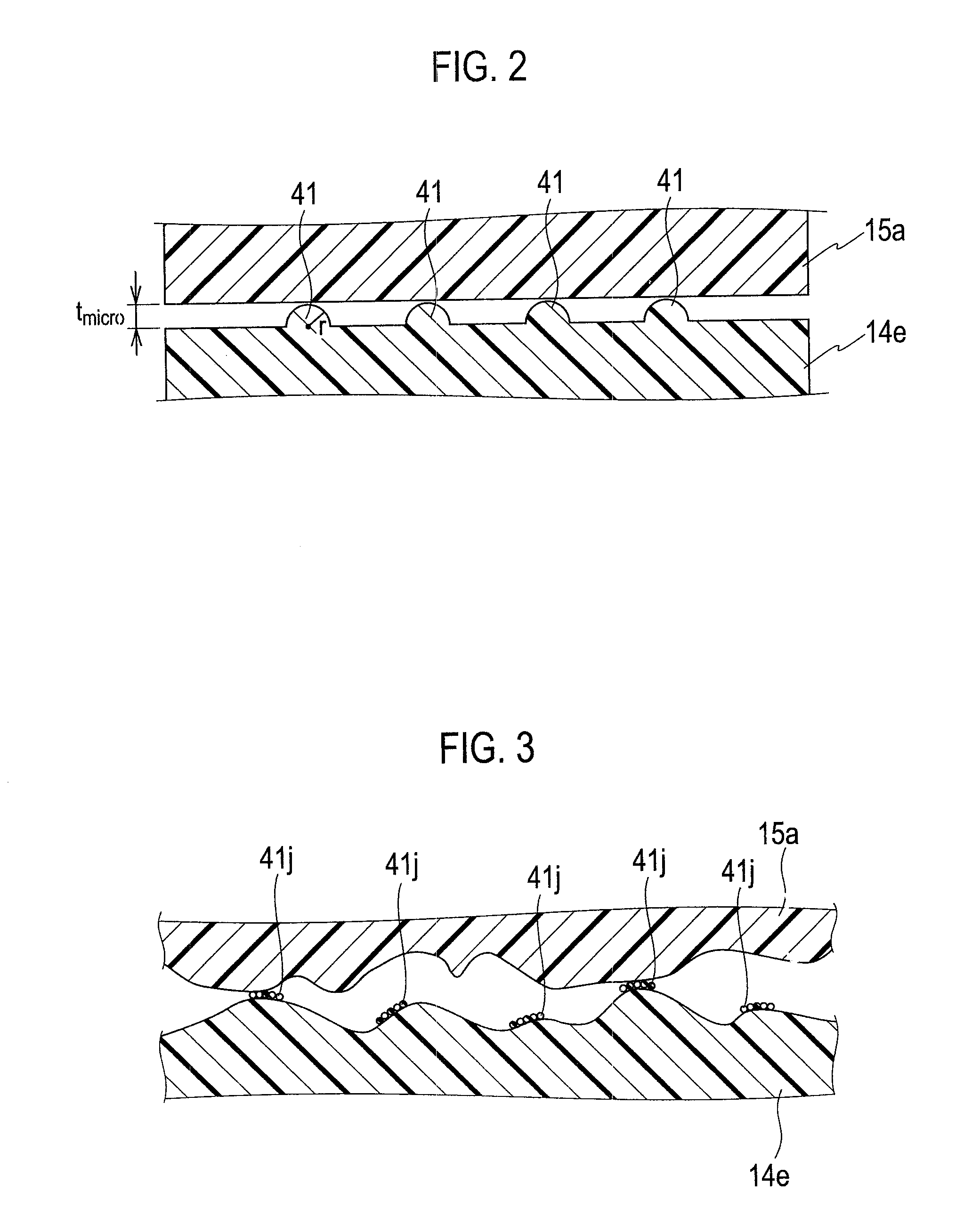
[0079]As illustrated in FIG. 1, an electro-mechanical transducer according to a first embodiment of the present invention is a ultrasonic probe encompassing a vibrating plate 15 that has a flat vibration surface under no load condition; an electret layer 13 in which polarization directions are aligned, defined by a flat first principal surface facing to the vibration surface of the vibrating plate 15 and a second principal surface facing in parallel to the first principal surface; a back electrode 17 in contact with the second principal surface of the electret layer 13; and amplifying means (19, 9) connected between the vibrating plate 15 and the back electrode 17. The back electrode 17 and the electret layer 13 may be metallurgically joined or may be adhered by an adhesive agent and the like, or may be merely brought into contact by a mechanical pressure. Although the illustrations on a plan view or a bird's eye view are omitted, each of the vibrating plate 15, the electret layer 1...

second embodiment

[0130]As illustrated in FIG. 15, an electro-mechanical transducer according to a second embodiment of the present invention is a hydrophone which encompasses a vibrating plate 15 that contains a vibrating electrode 15b made of conductor having a flat vibration surface; an electret layer 13 which is defined by the flat first principal surface facing to the vibration surface of the vibrating plate 15 and the second principal surface facing in parallel to the first principal surface and in which the polarization directions are aligned; a back electrode 17 in contact with the second principal surface of the electret layer 13; and amplifying means (19, 9) connected between the vibrating plate 15 and the back electrode 17. As described in the first embodiment, the back electrode 17 and the electret layer 13 may be metallurgically joined or may be adhered by adhesive agent and the like or may be merely brought into contact by the mechanical pressure. The vibrating plate 15 contains a vibra...

third embodiment

[0139]As illustrated in FIG. 17, an electro-mechanical transducer according to a third embodiment of the present invention is an ultrasonic sensor which encompasses a vibrating plate 15 that contains a vibrating electrode 15b made of conductor having a flat vibration surface; an electret layer 13 which is defined by the flat first principal surface facing to the vibration surface of the vibrating plate 15 and the second principal surface facing in parallel to the first principal surface and in which the polarization directions are aligned; a back electrode 17 in contact with the second principal surface of the electret layer 13; and amplifying means (19, 9) connected between the vibrating plate 15 and the back electrode 17. Similarly to the first and second embodiments, the back electrode 17 and the electret layer 13 may be metallurgically joined or may be adhered by adhesive agent and the like or may be merely brought into contact by the mechanical pressure. Although the illustrati...


PUM


Abstract

An electro-mechanical transducer contains a vibrating electrode (15b), a vibrating-electrode-insulating film (15a) disposed at a bottom surface of the vibrating electrode (15b), an electret layer (13) facing to the vibrating electrode (15b), an electret-insulating layer (14e) joined to a top surface of the electret layer (13), and a back electrode 17 in contact with a bottom surface of the electret layer (13). A microgap between ten nanometers and 100 micrometers is established between the vibrating-electrode-insulating film (15a) and electret-insulating layer (14e). A central line average roughness Ra of the vibrating electrode (15b), including a bending, is 1/10 or less of a gap width measured between the bottom surface of the vibrating electrode (15b) and the top surface of the electret layer (13).

Description

FIELD OF THE INVENTION[0001]The present invention pertains to electro-mechanical transducers and electro-mechanical converters, which convert mechanical vibrations into electric signals, and manufacturing methods of the electro-mechanical transducers and the electro-mechanical converters.DESCRIPTION OF THE RELATED ART[0002]In a mobile telephone and the like, microphones are required to be miniaturized for the sake of space-saving design. Also, as a pickup microphone for acoustic equipment, a small microphone that can be easily incorporated into musical instrument, such as a guitar and the like, is required. In particular, in order to make the mobile telephone or the like waterproof, there is the demand for a miniaturized waterproof microphone.[0003]A certain kind of polymers, such as polycarbonate and the like, has a property that, when a high electric field is applied from outside, charges induced on a surface are quasi-permanently held. O. Heaviside coined the term “electret” for ...

Claims


Application Information

Patent Timeline
IPC IPC(8): H01L29/84H01L21/60
CPCB06B1/0292H04R19/005H04R19/016H01L2924/0002H01L2924/00
Inventor KAGEYAMA, KENSUKE
Owner SAITAMA UNIVERSITY
Why Eureka
Try Eureka