Battery-dedicated electrode foil, positive electrode plate, battery, vehicle, and battery-equipped appliance, and manufacture method for the battery-dedicated electrode foil, and manufacture method of the positive electrode plate

a manufacturing method and technology of positive electrode, applied in the manufacture of final products, cell components, sustainable manufacturing/processing, etc., can solve the problems of low electrical conductivity between aluminum electrode foil and positive electrode active material, insufficient corrosion resistance of aluminum oxide layer, and risk of corrosion

Active Publication Date: 2011-05-12
TOYOTA JIDOSHA KK
View PDF3 Cites 20 Cited by
  • Summary
  • Abstract
  • Description
  • Claims
  • Application Information

AI Technical Summary

Benefits of technology

[0068]In the case where a water-based active material paste containing a Li compound is used, the water-based active material paste itself is a strong alkali due to the Li compound, and therefore, if the paste is applied to a battery-dedicated electrode foil, it is likely that the aluminum constituting the battery-dedicated electrode foil will be corroded to produce hydrogen gas and therefore a positive electrode active material layer containing a multiplicity of gaps therein will be formed. However, in the positive electrode plate manufacture method of the invention, since the battery-dedicated electrode foil used in the method is a battery-dedicated electrode foil as described above, that is, a battery-dedicated electrode foil provided with a corrosion-resistant layer, or with a corrosion-resistant layer and a diamond-like carbon coating formed on the corrosion-resistant layer, the use of the water-based active material paste does not corrode the battery-dedicated electrode foil, but allows formation of a dense and closely-packed positive electrode active material layer in which the formation of air spaces is restrained.

Problems solved by technology

Therefore, if a positive electrode active material is formed on such an aluminum electrode foil, the electroconductivity between the aluminum electrode foil and the positive electrode active material tends to be low.
Besides, the aluminum oxide layer is not sufficiently corrosion-resistant, and there is a risk of corrosion being caused by a positive electrode active material paste applied thereto, or by an electrolyte solution in the battery.
However, in the case where a carbon film is formed as in JP-A-10-106585 and JP-A-11-250900, an attempt to form the film by the sputtering process, which has high mass productivity, often results in formation of an insulating diamond-like carbon (DLC) film, and thus involves a risk of reducing the electroconductivity.
The use of platinum or gold, on the other hand, is costly, and may not be practical.

Method used


Image

  • Battery-dedicated electrode foil, positive electrode plate, battery, vehicle, and battery-equipped appliance, and manufacture method for the battery-dedicated electrode foil, and manufacture method of the positive electrode plate
  • Battery-dedicated electrode foil, positive electrode plate, battery, vehicle, and battery-equipped appliance, and manufacture method for the battery-dedicated electrode foil, and manufacture method of the positive electrode plate
  • Battery-dedicated electrode foil, positive electrode plate, battery, vehicle, and battery-equipped appliance, and manufacture method for the battery-dedicated electrode foil, and manufacture method of the positive electrode plate

Examples


embodiment 1

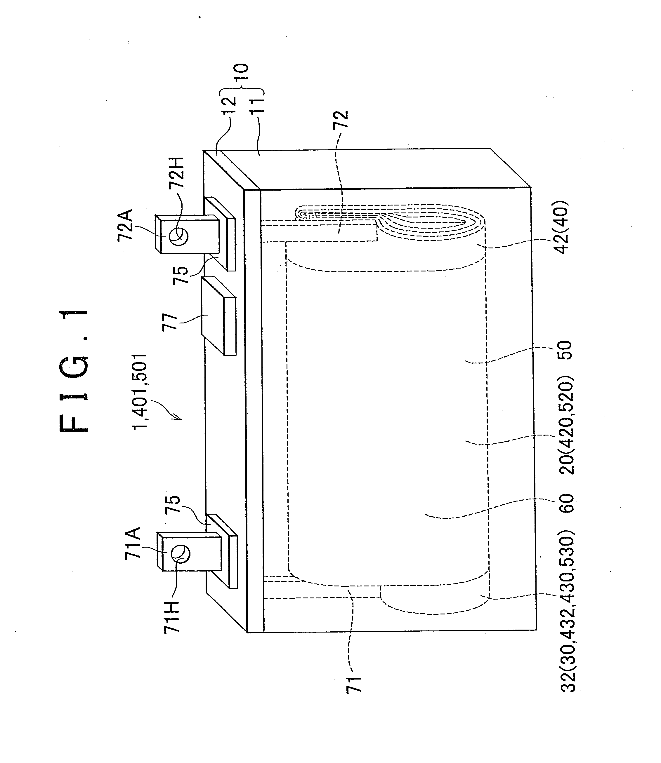
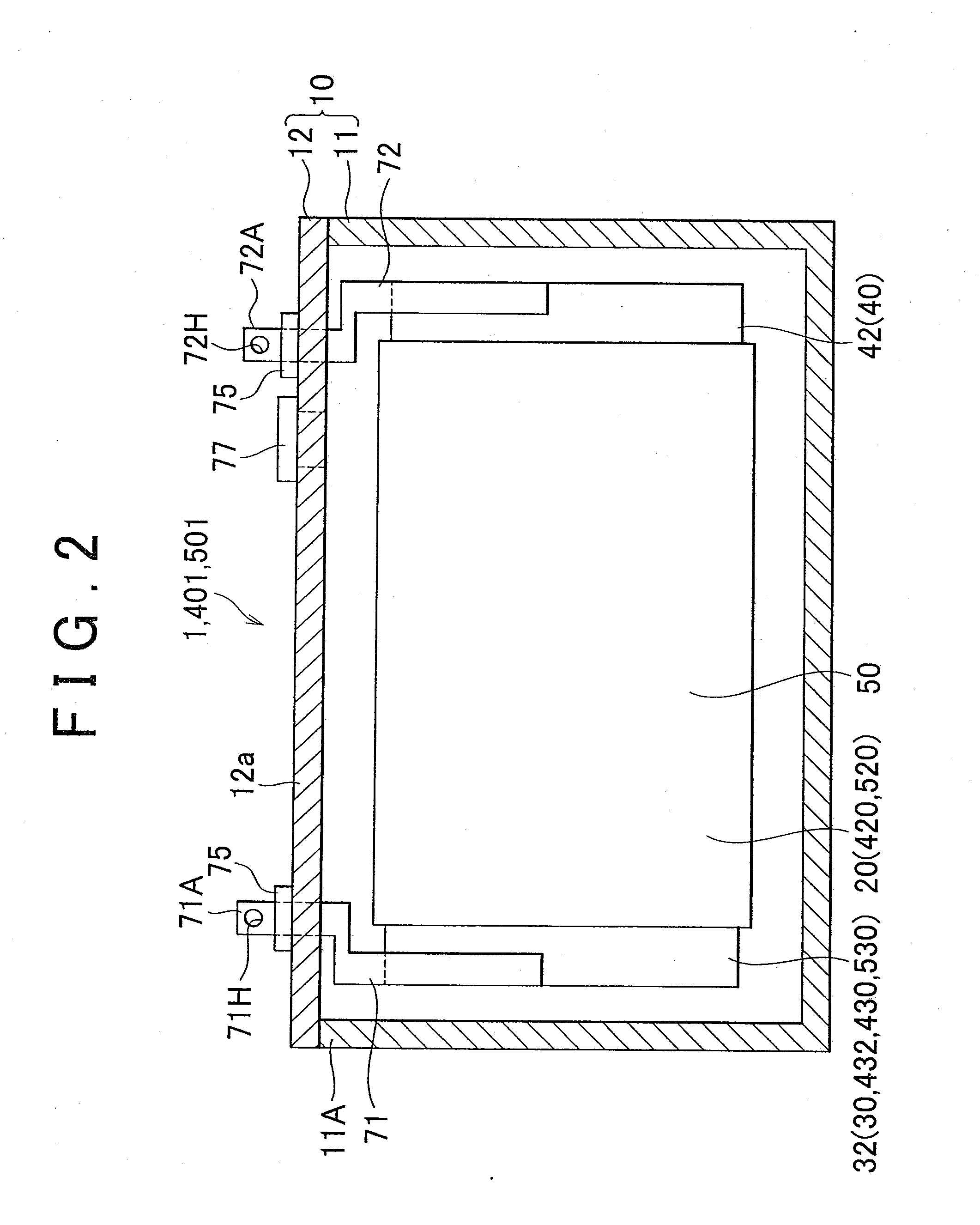
[0089]Embodiment 1 of the invention will be described with reference to the drawings. Firstly, a battery 1 in accordance with Embodiment 1 will be described. FIG. 1 is a perspective view of the battery 1, and FIG. 2 shows a partially cut-away cross-sectional view of the battery 1. The battery 1 in accordance with Embodiment 1 is a wound-type lithium-ion secondary battery that includes a power generation element 20, and an electrolyte solution 60. In this battery 1, the power generation element 20 and the electrolyte solution 60 are housed in a rectangular box-shape battery case 10. The battery case 10 has an battery case main body 11 and a sealing lid 12. Among the components of the battery case 10, the battery case main body 11 has a bottomed rectangular box shape, and a resin-made insulating film (not shown) is affixed to the entire inside surfaces of the battery case main body 11.

[0090]The sealing lid 12 has a rectangular platy shape, and closes an opening portion 11A of the batt...

modification 1

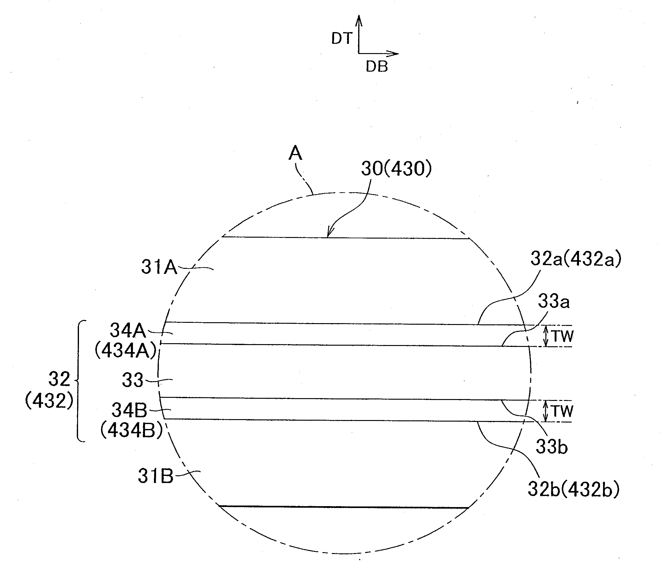
[0137]A battery 401 in accordance with Modification 1 of the invention will be described with reference to the drawings. The battery 401 of Modification 1 is different from the foregoing battery of Embodiment 1 in that a first corrosion-resistant layer and a second corrosion-resistant layer that are made of tungsten trioxide are formed on the first foil surface and the second foil surface, respectively, of the aluminum electrode foil, and is substantially the same in the other respects. The differences of Modification 1 from Embodiment 1 will be mainly described below, and the description of substantially the same portions thereof as those of Embodiment 1 will be omitted or simplified. Incidentally, substantially the same portions bring about substantially the same operation and effects. Besides, the portions substantially the same in operation and the like are represented by the same reference characters in the drawings and the following description.

[0138]A battery 401 in accordanc...

modification 2

[0149]Next, a battery 501 in accordance with Modification 2 of the invention will be described with reference to the drawings. The battery 501 of Modification 2 is different from the battery 1 of Embodiment 1 in that a diamond-like carbon coating is formed on the positive electrode active material layers of a positive electrode plate, and is substantially the same in the other respects as the battery 1 of Embodiment 1. The differences of Modification 2 from Embodiment 1 will be mainly described below, and the description of substantially the same portions thereof as those of Embodiment 1 will be omitted or simplified. Incidentally, substantially the same portions bring about substantially the same operation and effects. Besides, the portions substantially the same in operation and the like are represented by the same reference characters in the drawings and the following description.

[0150]A battery 501 in accordance with Modification 2 is a wound-type lithium-ion secondary battery t...


PUM

PropertyMeasurementUnit
thicknessaaaaaaaaaa
thicknessaaaaaaaaaa
thicknessaaaaaaaaaa

Abstract

A battery-dedicated electrode foil (32) includes an aluminum electrode foil (33) in which metal aluminum is exposed, and corrosion-resistant layers (34A, 34B) that are formed on surfaces (33a, 33b) of the aluminum electrode foil, and that are in direct contact with the metal aluminum that forms the aluminum electrode foil, and that is made of tungsten carbide.

Description

BACKGROUND OF THE INVENTION[0001]1. Field of the Invention[0002]The invention relates to a battery-dedicated electrode foil for use in a positive electrode plate of a battery, a positive electrode plate, a battery, and a vehicle and a battery-equipped appliance that employ the battery as well as a manufacture method for the battery-dedicated electrode foil, and a manufacture method for the positive electrode plate.[0003]2. Description of the Related Art[0004]In recent years, along with the wide-spread use of portable electronic appliances, such as cellular phones, notebook type personal computers, video camcorders, etc., and vehicles, such as hybrid electric motor vehicles and the like, the demand for batteries for use as power sources for driving these devices is increasing. Among these batteries, there exist batteries that employ a positive electrode foil whose base material is an aluminum electrode foil. Examples of such batteries include a lithium-ion battery that employs a posi...

Claims


Application Information

Patent Timeline
Patent Type & Authority Applications(United States)
IPC IPC(8): H01M10/26H01M4/66H01M4/58H01M4/139B05D5/12H01B13/00H01M4/131H01M4/1391H01M4/64H01M10/052H01M10/0525H01M10/0566H01M10/0568
CPCH01M4/663H01M4/661Y02E60/122H01M4/139H01M4/1391H01M10/0568Y02T10/7011Y10T29/49115H01M4/667H01M10/052H01M4/664Y02E60/10Y02T10/70Y02P70/50
Inventor UCHIDA, YOZOTERANISHI, TADASHI
Owner TOYOTA JIDOSHA KK
Why Eureka
Try Eureka