Two Fin Swimming Apparatus

a technology of swimming apparatus and fins, applied in the direction of swimming aids, sports apparatus, propulsive elements, etc., can solve the problems of ordinary fins or monofins, low swimming efficiency, low and achieve the effect of improving the ratio between momentum and general stroke effor

Active Publication Date: 2011-05-12
PAKHOMOV DMITRIY VIACHESLAVOVICH
View PDF7 Cites 1 Cited by
  • Summary
  • Abstract
  • Description
  • Claims
  • Application Information

AI Technical Summary

Benefits of technology

[0007]The invention utilizes the fact that a fin in the shape of a wing provides a better ratio between the momentum and the ...

Problems solved by technology

The disadvantage of ordinary fins or monofins is low swimming efficiency because of imperfect hydrodynamics caused by the elongated form and the flatness of the fin blade.
Wh...

Method used


Image

  • Two Fin Swimming Apparatus
  • Two Fin Swimming Apparatus
  • Two Fin Swimming Apparatus

Examples


Embodiment Construction

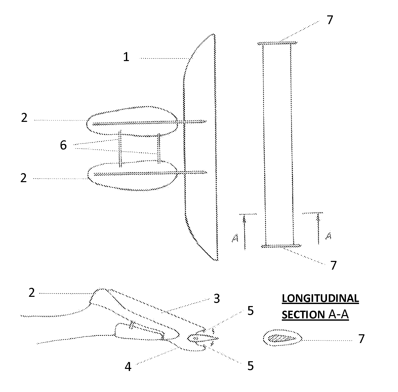
[0033]The swimming apparatus pertains to swimming with special equipment and can be used for increasing speed, comfortable maneuvering, and making swimming more economical. It is intended for entertainment and sports.

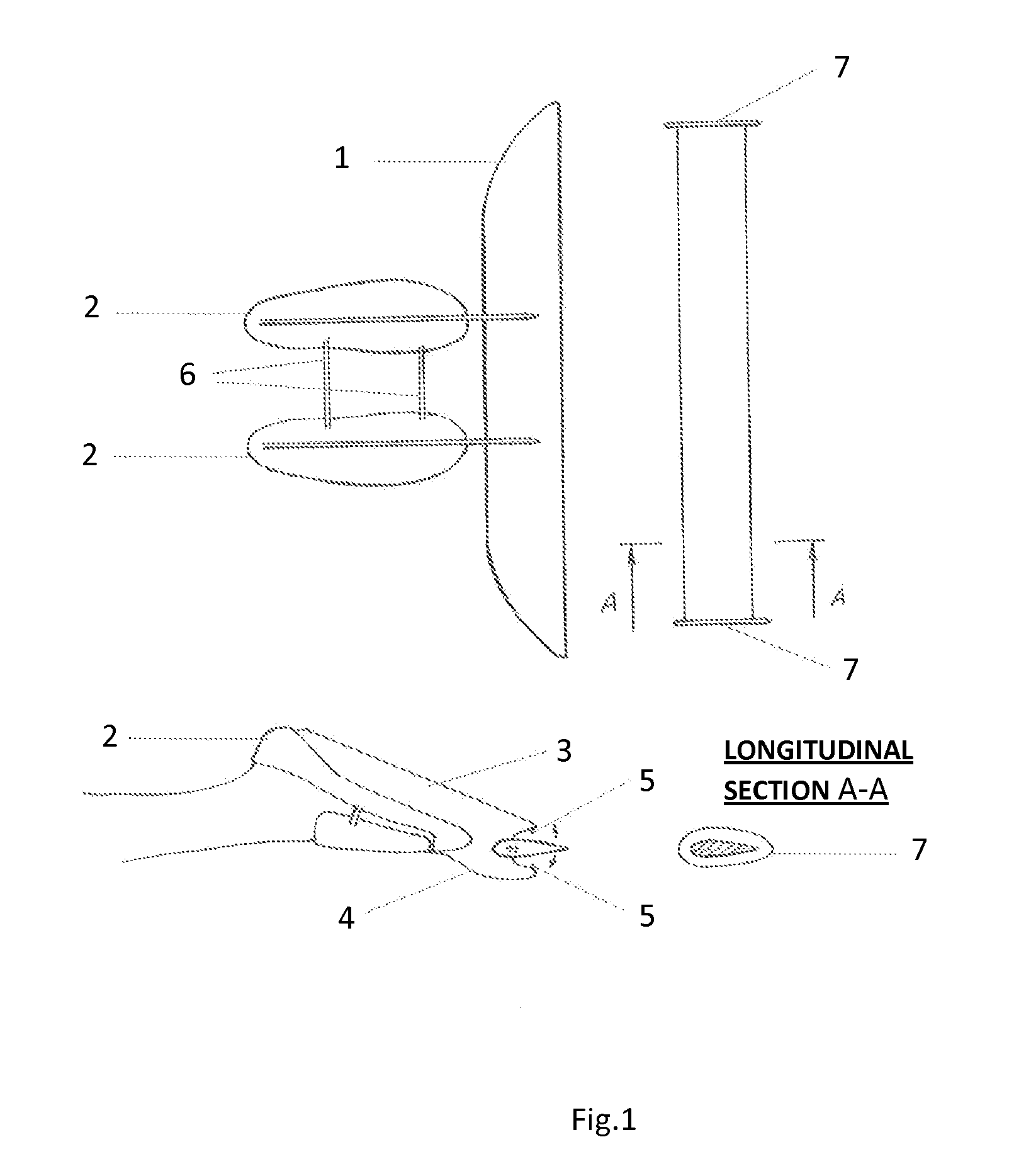
[0034]The objective of the invention is to provide a quicker means of swimming than ordinary fins and monofins. The tail fin serves the purpose of optimizing the kick more than ordinary fins. The tail fin characteristics are fulfilled to achieve the optimal ratio of momentum to the general stroke effort. The tail fin width (transverse direction towards the movement) is several times wider than its length (lengthwise direction towards the movement). The tail fin longitudinal section has a shape which provides the optimal ratio of lift (which appears on the fin surface while water flows over the fin) to resistance. The tail fin construction allows one to achieve a maximum effect for both a downstroke and an upstroke because it sets an optimal attack angle of the tail fin ...


PUM


Abstract

The swimming apparatus pertains to swimming with special equipment for swimmers and divers and can be used for increasing speed, comfortable maneuvering, and making swimming more economical. The swimming apparatus comprises a tail fin, a hand-held fin and a dual snorkel.

Description

CROSS-REFERENCE TO RELATED APPLICATION[0001]This U.S. patent application claims priority under 35 U.S.C. 119 (a) through (d) of Russian Federation utility application RU 2009141540 filed on Nov. 11, 2009, hereby entirely incorporated by reference.BACKGROUND OF THE INVENTION[0002]The swimming apparatus pertains to swimming with special equipment for swimmers and divers and can be used for increasing speed, comfortable maneuvering, and making swimming more economical. The swimming apparatus comprises a tail fin, a hand-held fin and a dual snorkel.[0003]The disadvantage of ordinary fins or monofins is low swimming efficiency because of imperfect hydrodynamics caused by the elongated form and the flatness of the fin blade.[0004]When water flows over the fin while stroking, there is a stalling (turbulence) on the fin / monofin surface which causes a low ratio between the momentum and the general stroke effort. This is the reason for the lower swimming speed and faster fatigue while kicking...

Claims


Application Information

Patent Timeline
IPC IPC(8): A63B31/10A63B31/11
CPCA63B31/10A63B31/11B63H16/08B63H1/36A63B2208/028
Inventor PAKHOMOV, DMITRIY VIACHESLAVOVICH
Owner PAKHOMOV DMITRIY VIACHESLAVOVICH
Why Eureka
Try Eureka