Nasal pillows with high volume bypass flow and method of using same

a bypass flow and high-volume technology, applied in the field of nasal pillows with high-volume bypass flow and method of using same, can solve the problems of user wake-up, leakage around the edges of the mask, and inability to provide a fixed pressure for all flow levels, so as to reduce the effort required, shorten the pressure, and fall asleep easier

Active Publication Date: 2011-05-19
FISHER & PAYKEL HEALTHCARE LTD
View PDF26 Cites 52 Cited by
  • Summary
  • Abstract
  • Description
  • Claims
  • Application Information

AI Technical Summary

Benefits of technology

[0019]Ramping is possible with some blowers. This is a method used at the beginning of a users sleep cycle to allow the user to fall asleep more easily. The pressure provided by the blower at the start of a sleep cycle is lower than what is ideally required. The pressure provided by the blower is gradually increased to the prescribed level over a period of time, allowing the user...

Problems solved by technology

However, in reality, it is almost impossible to provide a fixed pressure for all flow levels.
Another disadvantage that some users can experience when using a mask as their interface is as follows: when the user exhales against an incoming pressurised stream of gases, this can cause leaks around the edges of the mask as the mask partially lifts away from, or is pushed off, the surface of a user's face.
This can cause a user to wake up as gases wash across their face or jet into their eyes.
This can lead to the mask feeling uncomfortable for a user and with time can cause pressure sores and/or soft-tissue abrasions at the nasal bridge.
The user can in response discontinue their therapy, or at least be unfavourably inclined towards continuing.
If the mask or patient interface is provided with bias vent holes, there is always going to be some level of leakage through the vent holes.
However, a portion of the heated, humidified gases is lost (sacrificed) before teaching the user.
Therefore, the amount of leak from around the cannula is unknown and uncontrollable, even when the pressure at the cannula is known, and the pressure delivered to the nares is unknown or uncontrollable even if the flow delivered to the cannula is known.
Also, when using a cannula, it is impossible to avoid the entrainment of dry, unheated atmospheric air into the nostrils of a user.
Another problem encountered with unsealed high flow nasal cannula is the noise that is generated by air flowing between the nares and the outside of the nasal cannula.
This can be especially problematic when a nearly constant flow is provided to the user.
In this situation the flow exiting to atmosphere varies significantly as the patient exhales and inhales creating noise that varies in intensity over the breath cycle.
The amount of noise is strongly dependant on the position and orientation of the cannula in nares as this affects the velocity of the exhaust (leaked) gas.
This can be difficult to achieve reliably due to the unknown resistance to flow of air passing between outside of the cannula and the inside of the nares.
However, it can be difficult to exhale against the stream o...

Method used


Image

  • Nasal pillows with high volume bypass flow and method of using same
  • Nasal pillows with high volume bypass flow and method of using same
  • Nasal pillows with high volume bypass flow and method of using same

Examples


Embodiment Construction

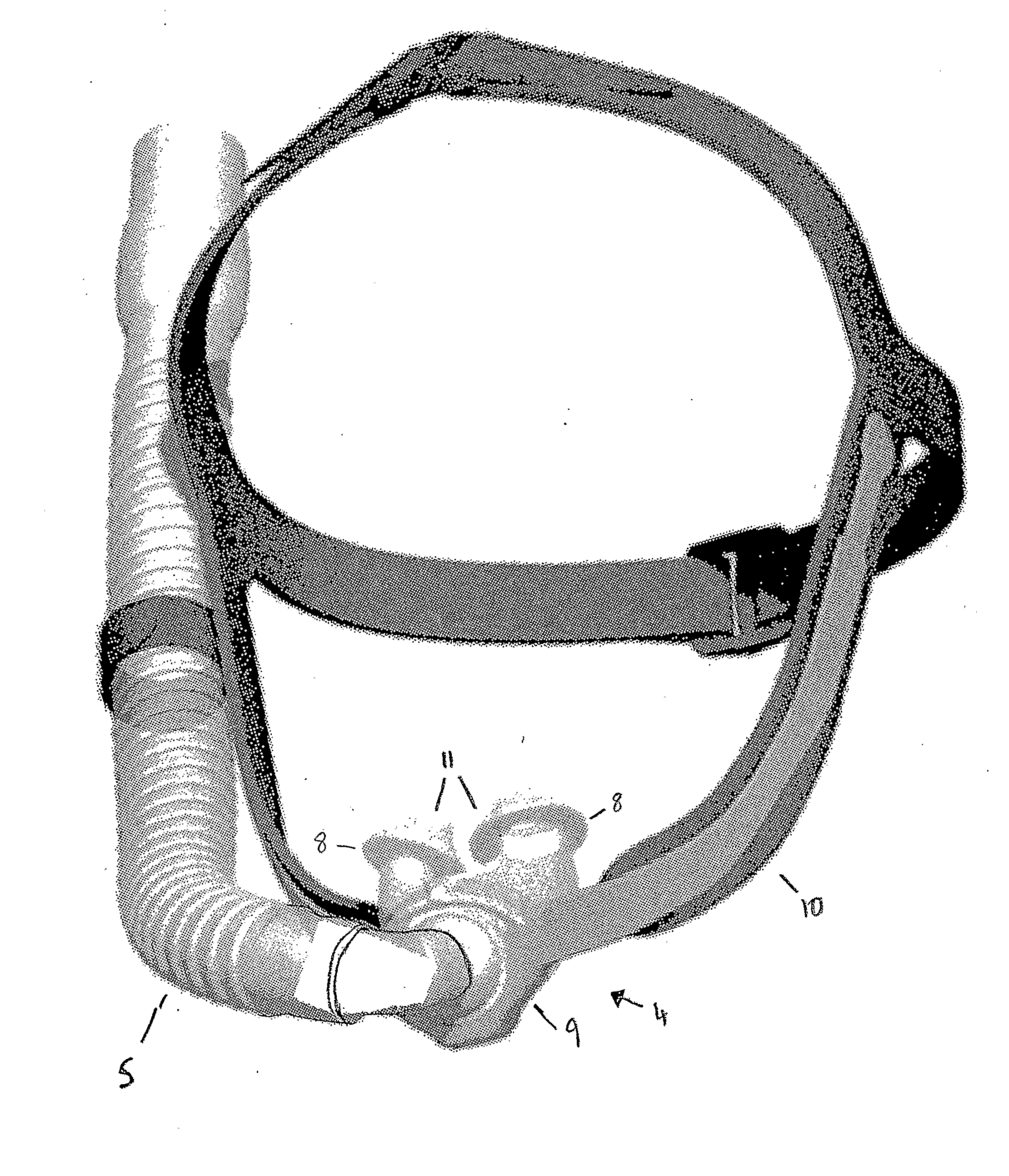
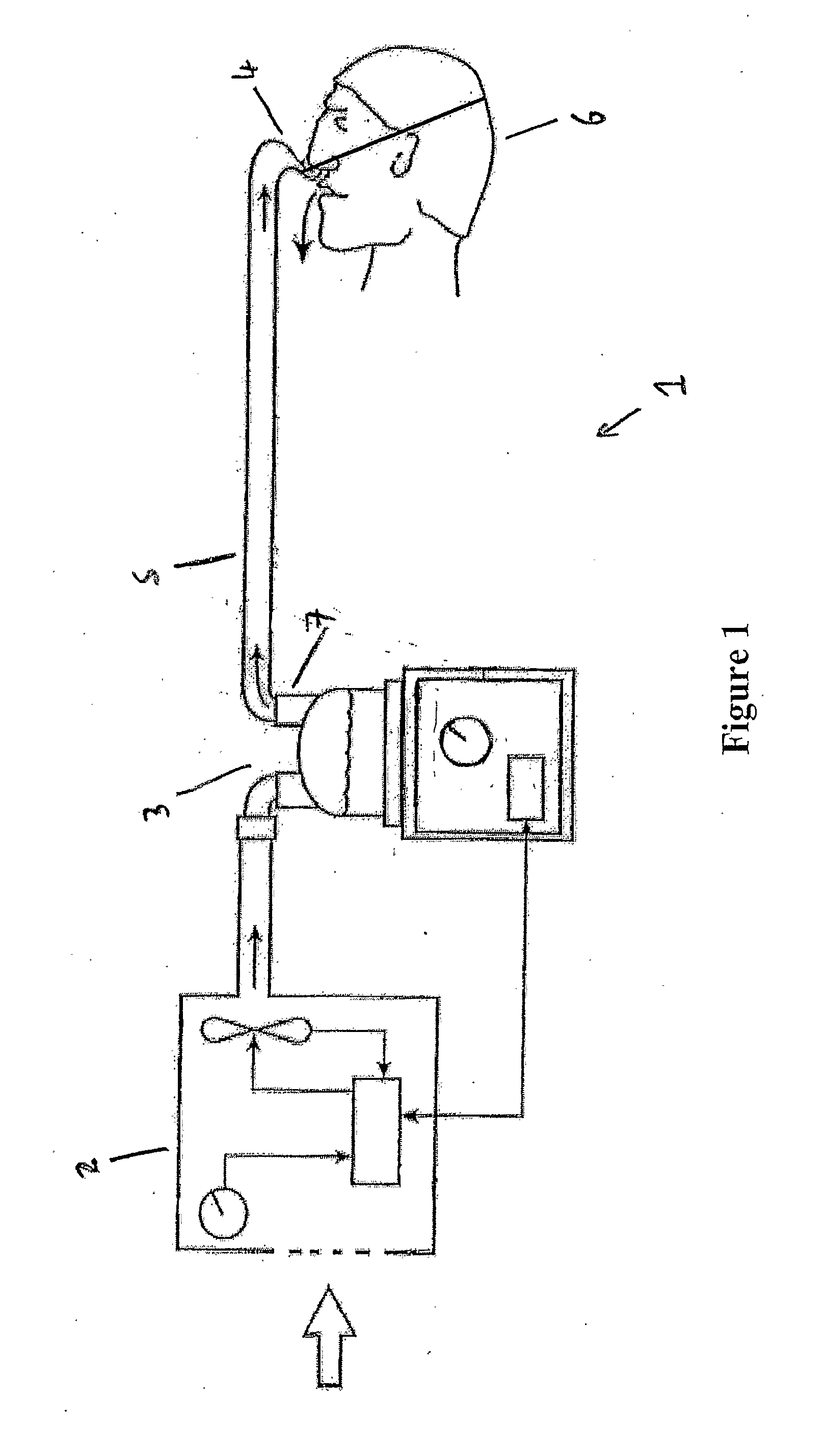
[0116]The present invention will be described with reference to a gases supply system 1 comprising four main parts: a blower unit 2, a humidifier unit 3 connected to the blower unit 2, a patient interface 4, and a conduit 5 connecting the patient interface 4 with the humidifier unit 3. In the example system shown in FIG. 1, the humidifier unit 3 is separate to the blower unit 2 (which can also be referred to as a respirator unit or gases supply unit). Systems of this type where the humidifier unit 3 and the blower unit 2 are separate items are usually referred to as modular systems. Systems where the blower unit and the humidifier unit are rigidly connected can be referred to as integrated units. However, it should be noted that the invention is equally applicable to either a modular system (a system where the humidifier unit 3 and the blower unit 2 are separate and connected by a flexible conduit or similar), or an integrated system.

[0117]It is not necessary to describe all the det...


PUM


Abstract

A fan unit which in use forms part of a gases supply unit, the gases supply unit suitable for use as part of a system for providing heated humidified gases to a user, the fan unit having a casing that has an inlet aperture and an outlet passage, the outlet passage including an exit aperture, the fan unit also including a fan which is located inside the casing and which is adapted for connection to a motor to drive rotation of the fan in use, the fan drawing gases into the casing via the inlet aperture, and forcing these gases out of the casing via the outlet passage as a gases stream, the outlet passage further including at least one bypass vent hole independent of the exit aperture and arranged at an angle to the path of the gases stream through the outlet passage.

Description

BACKGROUND OF THE INVENTION[0001]1. Field of the Invention[0002]This invention relates to devices for providing a flow of gases at a pressure above atmospheric pressure to a user for therapeutic purposes.[0003]This invention also relates to patient interfaces for use with devices which provide a gases stream at a pressure above atmospheric to a user for therapeutic purposes.[0004]This invention also relates to methods of using patient interfaces of known geometry and dimensions to provide improved real time adjustment of the characteristics of a gases stream provided to a user for therapeutic purposes.[0005]This invention also relates to methods of using patient interfaces of known geometry and dimensions to improve the initial or in-use characteristics of a gases stream provided to a user for therapeutic purposes.[0006]2. Summary of the Prior Art[0007]Devices or systems for providing a humidified gases flow to a patient for therapeutic purposes are well known in the art. Systems fo...

Claims


Application Information

Patent Timeline
IPC IPC(8): A61M16/00
CPCA61M16/06A61M16/0666A61M16/0683A61M16/0858A61M2016/0027A61M2016/0033A61M2210/0618A61M16/16A61M16/0003A61M16/0069A61M2016/003A61M2205/3334
Inventor MCAULEY, ALASTAIR EDWINMAKINSON, IAN DOUGLASCRESSWELL, FIONA ELIZABETH
Owner FISHER & PAYKEL HEALTHCARE LTD
Why Eureka
Try Eureka